
User Manual
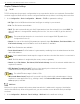
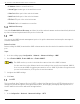
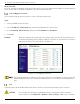
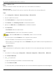
Table Of Contents
- Legal Information
- About this Manual
- Trademarks
- Disclaimer
- Symbol Conventions
- Safety Instruction
- Contents
- Chapter 1 System Requirements
- Chapter 2 Device Activation and Accessing
- Illegal Login Lock
- Chapter 3 Live View
- 3
- 3.1 Live View Parameters
- 3.1.1 Enable and Disable Live View
- 3.1.2 Adjust Aspect Ratio
- 3.1.3 Live View Stream Type
- 3.1.4 Select Third-Party Plug-in
- 3.1.5 Window Division
- 3.1.6 Light
- 3.1.7 Count Pixel
- 3.1.8 Start Digital Zoom
- 3.1.9 Auxiliary Focus
- 3.1.10 Lens Initialization
- 3.1.11 Quick Set Live View
- 3.1.12 Lens Parameters Adjustment
- 3.1.13 Conduct 3D Positioning
- 3.2 Set Transmission Parameters
- 3.3 Set Smooth Streaming
- Chapter 4 Video and Audio
- Chapter 5 Video Recording and Picture Capture
- Chapter 6 Events and Alarms
- 6
- 6.1 Basic Event
- 6.2 Smart Event
- 6.2.1 Detect Audio Exception
- 6.2.2 Set Defocus Detection
- 6.2.3 Detect Scene Change
- 6.2.4 Set Face Detection
- 6.2.5 Set Video Loss
- 6.2.6 Set Intrusion Detection
- 6.2.7 Set Line Crossing Detection
- 6.2.8 Set Region Entrance Detection
- 6.2.9 Set Region Exiting Detection
- 6.2.10 Set Unattended Baggage Detection
- 6.2.11 Set Object Removal Detection
- 6.2.12 Draw Area
- 6.2.13 Set Size Filter
- Chapter 7 Network Settings
- Chapter 8 Arming Schedule and Alarm Linkage
- Chapter 9 System and Security
- 9
- 9.1 View Device Information
- 9.2 Search and Manage Log
- 9.3 Simultaneous Login
- 9.4 Import and Export Configuration File
- 9.5 Export Diagnose Information
- 9.6 Reboot
- 9.7 Restore and Default
- 9.8 Upgrade
- 9.9 View Open Source Software License
- 9.10 Time and Date
- 9.11 Set RS-485
- 9.12 Set RS-232
- 9.13 External Device
- 9.14 Security
- 9.15 Certificate Management
- 9.16 User and Account
- Chapter 10 Allocate VCA Resource
- Chapter 11 Open Platform
- Chapter 12 Set EPTZ
- Chapter 13 Smart Display
- Appendix A: Device Command
- Appendix B: Device Communication Matrix

iDS-2CD7xxG0-xxxxx Network Bullet Camera User Manual
UM iDS-2CD7xxG0-xxxxx 021021NA 52
Figure 6-9 Set Rule
5. Optional: Repeat the above steps to set more regions.
6. For the arming schedule settings, see Set Arming Schedule. For the linkage method settings, see
Linkage Method Settings.
7. Click Save.
The function is supported only by certain models. The actual display varies by model.
Draw Area
This section introduces the configuration of area.
Steps
1. Click Draw Area.
2. Click on the live view to draw the boundaries of the detection region, and right click to complete
drawing.
3. Click Save.
Click Clear All to clear all pre-defined areas.
Set Size Filter
This part introduces setting the size filter. Only a target whose size is between the minimum value and
maximum value is detected and triggers alarm.
Steps
1. Click Max. Size, and drag the mouse in the live view to draw the maximum target size.
2. Click Min. Size, and drag the mouse in the live view to draw the minimum target size.
3. Click Save.