
User Manual
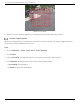
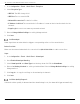
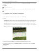
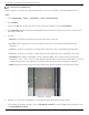
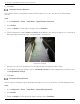
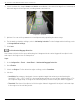
Table Of Contents
- Legal Information
- About this Manual
- Trademarks
- Disclaimer
- Symbol Conventions
- Safety Instruction
- Contents
- Chapter 1 System Requirements
- Chapter 2 Device Activation and Accessing
- Illegal Login Lock
- Chapter 3 Live View
- 3
- 3.1 Live View Parameters
- 3.1.1 Enable and Disable Live View
- 3.1.2 Adjust Aspect Ratio
- 3.1.3 Live View Stream Type
- 3.1.4 Select Third-Party Plug-in
- 3.1.5 Window Division
- 3.1.6 Light
- 3.1.7 Count Pixel
- 3.1.8 Start Digital Zoom
- 3.1.9 Auxiliary Focus
- 3.1.10 Lens Initialization
- 3.1.11 Quick Set Live View
- 3.1.12 Lens Parameters Adjustment
- 3.1.13 Conduct 3D Positioning
- 3.2 Set Transmission Parameters
- 3.3 Set Smooth Streaming
- Chapter 4 Video and Audio
- Chapter 5 Video Recording and Picture Capture
- Chapter 6 Events and Alarms
- 6
- 6.1 Basic Event
- 6.2 Smart Event
- 6.2.1 Detect Audio Exception
- 6.2.2 Set Defocus Detection
- 6.2.3 Detect Scene Change
- 6.2.4 Set Face Detection
- 6.2.5 Set Video Loss
- 6.2.6 Set Intrusion Detection
- 6.2.7 Set Line Crossing Detection
- 6.2.8 Set Region Entrance Detection
- 6.2.9 Set Region Exiting Detection
- 6.2.10 Set Unattended Baggage Detection
- 6.2.11 Set Object Removal Detection
- 6.2.12 Draw Area
- 6.2.13 Set Size Filter
- Chapter 7 Network Settings
- Chapter 8 Arming Schedule and Alarm Linkage
- Chapter 9 System and Security
- 9
- 9.1 View Device Information
- 9.2 Search and Manage Log
- 9.3 Simultaneous Login
- 9.4 Import and Export Configuration File
- 9.5 Export Diagnose Information
- 9.6 Reboot
- 9.7 Restore and Default
- 9.8 Upgrade
- 9.9 View Open Source Software License
- 9.10 Time and Date
- 9.11 Set RS-485
- 9.12 Set RS-232
- 9.13 External Device
- 9.14 Security
- 9.15 Certificate Management
- 9.16 User and Account
- Chapter 10 Allocate VCA Resource
- Chapter 11 Open Platform
- Chapter 12 Set EPTZ
- Chapter 13 Smart Display
- Appendix A: Device Command
- Appendix B: Device Communication Matrix

iDS-2CD7xxG0-xxxxx Network Bullet Camera User Manual
UM iDS-2CD7xxG0-xxxxx 021021NA 47
3. See Set Arming Schedule for setting scheduled time. See Linkage Method Settings for setting linkage
method.
4. Click Save.
Set Intrusion Detection
Detects objects entering and loitering in a pre-defined virtual region, after which the device can take
linkage actions.
Steps
1. Go to Configuration → Event → Smart Event → Intrusion Detection.
2. Check Enable.
3. Select a Region. For the detection region settings, refer to Draw Area.
4. Set rules.
• Sensitivity: Percentage of the body part of an acceptable target that enters the pre-defined region.
Sensitivity = 100 - S1/ST × 100. S1 is the target body part that crosses the pre-defined region. ST is
the complete target body. The higher the sensitivity value, the more easily the alarm is triggered.
• Threshold: The threshold for the time the object loiters in the region. If the time the object stays
exceeds the threshold, the alarm is triggered. The larger the value, the longer the alarm trigger time.
• Object: You can specify the object type to be detected.
Figure 6-4 Set Rule
5. Optional: You can set the parameters of multiple areas by repeating the above steps.
6. For arming schedule settings, see Set Arming Schedule. For linkage method settings, see Linkage
Method Settings.
7. Click Save.