
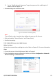
Quick Start Guide

QSG ECI-B62Z2 030618NA 6
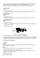
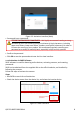
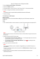
No. Components
2 O-Type Gasket
3 Network Plug
4 Water-Resistant Endcap
5 Water-Resistant Rubber Gasket
6 Lock Nut
7 Network Cable from Router/Switch
Steps:
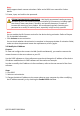
1. Feed the plugless network cable ⑦ through the lock nut ⑥, water-resistant rubber
gasket ⑤ (the rubber gasket inset ridge must face the water-resistant endcap), and the
water-resistant endcap ④.
2. Crimp an RJ-45 network plug ③ onto the end of the cable, making sure to insert the
twisted pairs of wires in the correct order.
3. Place the O-type gasket ② onto the end of the camera’s network interface socket ①.
4. Insert the network plug ③ into the camera’s network interface socket ①.
5. Insert the water-resistant rubber gasket ⑤ into the water-resistant endcap ④, and
secure the lock nut ⑥ with the water-resistant endcap ④.
6. Align the snap on the water-resistant endcap ④ with the notch on the camera’s network
interface socket ①, and then secure the water-resistant endcap ④ to the camera’s
network interface socket ① to finish installation.
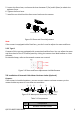
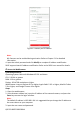
Camera
Switch/Router
Align the snap and notch.
i. Insert
⑤
into
④
.
ii. Secure
⑥
with
④
.
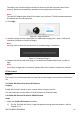
Water-Resistance Accessory Installation
Figure 2-11