Network Bullet Camera ECI-B62Z2 Quick Start Guide
Manual Illustrations and Features Graphics (screen shots, product pictures, etc.) in this document are for illustrative purposes only. Your actual product may differ in appearance. Your product might not support all features discussed in this document. Hikvision USA Inc., 18639 Railroad St., City of Industry, CA 91748, USA • Hikvision Canada, 4848 rue Levy, Saint Laurent, Quebec, Canada, H4R 2P1 Telephone: +1-909-895-0400 • Toll Free in USA: +1-866-200-6690 • E-Mail: sales.usa@hikvision.com • www.hikvision.
CONFORMS THE APPLICABLE LAW. HIKVISION SHALL NOT BE LIABLE IN THE EVENT THAT THIS PRODUCT IS USED WITH ILLEGITIMATE PURPOSES. IN THE EVENT OF ANY CONFLICTS BETWEEN THIS MANUAL AND THE APPLICABLE LAW, THE LATER PREVAILS. Regulatory Information FCC Information Please take attention that changes or modification not expressly approved by the party responsible for compliance could void the user’s authority to operate the equipment.
Safety Instruction These instructions are intended to ensure that user can use the product correctly to avoid danger or property loss. The precaution measure is divided into “Warnings” and “Cautions” Warnings: Serious injury or death may occur if any of the warnings are neglected. Cautions: Injury or equipment damage may occur if any of the cautions are neglected. Warnings Follow these safeguards to prevent serious injury or death.
● ● ● ● ● ● ● Do not place the camera in extremely hot, cold (the operating temperature shall be -30° to +60° C, or -40° to 60° C if the camera model has an “H” in its suffix), dusty or damp locations, and do not expose it to high electromagnetic radiation. To avoid heat accumulation, good ventilation is required for operating environment. Keep the camera away from liquid while in use. While in delivery, the camera shall be packed in its original packing, or packing of the same texture.
Table of Contents 1 Appearance Description ................................................................................................................................................. 0 1.1 Type I Camera.................................................................................................................................................. 0 1.2 Type II Camera.........................................................................................................................................
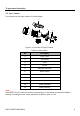
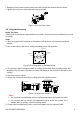
1 Appearance Description 1.1 Type I Camera The overview of the type I camera is shown below. 2 1 3 7 8 9 10 4 D C12V IN 11 56 Figure 1-1 Overview of Type I Camera Table 1-1 Description No.
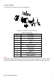
1.2 Type II Camera The overview of the type II camera is shown below. 2 1 3 7 8 9 4 DC12 VI N 10 56 Figure 1-2 Overview of Type II Camera Table 1-2 Description No.
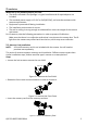
2 Installation Make sure of the following before you start: ● The device included in the package is in good condition and all required parts are included. ● The standard power supply is 12 VDC or PoE (802.3af), and must be consistent with camera requirements. ● Equipment is powered-off during installation. ● The installation environment is correct. ● The wall or ceiling is strong enough to withstand four times the weight of the camera and mount.
4. Rotate the front cover clockwise back onto 5. Tighten the lock screw clockwise to the camera and replace the sun shield. fix the sun shield. IN 2 V D1 C Figure 2-4 Fix the Front Cover 2.2 Ceiling/Wall Mounting Before You Start: These types of cameras are equipped with a bracket. They can be mounted directly to a wall or ceiling. Steps: 1. Stick the supplied drill template to the wall or ceiling where you intend to install the camera. 2.
7. Power on the camera, and set the network configuration (for further detail, refer to the Network Camera LAN Configuration and Access via Web Browser sections) to check whether the image is at an optimum angle. If not, adjust the surveillance angle. Pan Adjustment Steps: 1). Loosen lock screw 1. 2). Adjust the panning position of the camera. The adjusting range is from 0° to 360°. 3). Tighten lock screw 1. Tilt Adjustment Steps: 1). Loosen lock screw 2. 2). Adjust the tilting position of the camera.
5. Loosen the focus lever, and move the lever between F (Far) and N (Near) to obtain the optimum focus. 6. Tighten the focus lever. 7. Install the sun shield and the front cover back onto the camera. Zoom/Focus Lever D C12V I N Figure 2-8 Zoom and Focus Adjustment Note: If the camera is equipped with a fixed lens, you don’t need to adjust the zoom and focus. 2.3.2 Type II Cameras of this type are equipped with a motorized varifocal lens.
No. Components 2 O-Type Gasket 3 Network Plug 4 Water-Resistant Endcap 5 Water-Resistant Rubber Gasket 6 Lock Nut 7 Network Cable from Router/Switch Steps: 1. Feed the plugless network cable ⑦ through the lock nut ⑥, water-resistant rubber gasket ⑤ (the rubber gasket inset ridge must face the water-resistant endcap), and the water-resistant endcap ④. 2. Crimp an RJ-45 network plug ③ onto the end of the cable, making sure to insert the twisted pairs of wires in the correct order. 3.
3 Camera LAN Configuration Note: The use of products with Internet access carries inherent security risks. In order to avoid network attacks and information leakage, strengthen your own network protection. If the product does not work properly, contact your dealer or the nearest service center for help. 3.
Figure 3-3 Activation Interface (Web) 3. Create and input a password. STRONG PASSWORD RECOMMENDED – We highly recommend creating a strong password of your own choosing (using a minimum of eight characters, including upper case letters, lower case letters, numbers, and special characters) in order to increase the security of your product. We recommend regularly resetting your password on a weekly or monthly basis, especially in high security systems. 4. Confirm the password. 5.
Note: SADP supports batch camera activations. Refer to the SADP user manual for further details. 3. Create, input, and confirm the password. STRONG PASSWORD RECOMMENDED – We highly recommend creating a strong password of your own choosing (using a minimum of 8 characters, including upper case letters, lower case letters, numbers, and special characters) in order to increase the security of your product.
Figure 3-5 Modify the IP Address Note: Hik-Connect can be enabled during activation. Refer to Chapter 5.1 for detailed information. 4. Input the admin password and click Modify to complete IP address modification. SADP supports batch IP address modification. Refer to the SADP user manual for details. 4 Access via Web Browser System Requirement: Operating System: Microsoft Windows XP SP1 and above CPU: 2.
The admin user should configure the device accounts and user/operator permissions properly. Delete the unnecessary accounts and user/operator permissions. Note: The device IP address gets locked if the admin user performs 7 failed password attempts (5 attempts for the user/operator). 4. Click Login. Figure 4-1 Login Interface 5. Install the plug-in before viewing the live video and managing the camera. Follow the installation prompts to install the plug-in.
2). For the “Modify Network Parameters” page that appears while modifying the IP address, refer to Chapter 3.3. 2. Create or change the verification code. Figure 5-1 Verification Code Setting (SADP) Note: The verification code is required when adding the camera to Hik-Connect. 3. Click and read the “Terms of Service” and “Privacy Policy.” 4. Confirm the settings. 5.2.1 Enable Hik-Connect via a Web Browser Before You Start: Activate the camera before enabling the service. Refer to Chapter 3.2.
Figure 5-2 Platform Access Configuration (Web) 3. Set the Platform Access Mode to Hik-Connect. 4. Check the Enable checkbox. 5. Click and read the “Terms of Service” and “Privacy Policy” in the pop-up window. 6. Create or change the verification code for the camera. Note: A verification code is required when you add the camera to Hik-Connect. 7. Save the settings. 5.3 Add Camera to Hik-Connect Before You Start: Enable Hik-Connect on the camera before adding it to your Hik-Connect account. See Chapter 5.1.
Note: For detailed information, refer to the Hik-Connect user manual. 5.4 Initialize the Memory Card Note: The microSD memory card is not included with the camera and must be purchased separately. Steps: 1. Check the status of the memory card by tapping on the Storage Status in the Device Settings interface. 2. If the memory card status displays as Uninitialized, tap to initialize it. The status will then change to Normal.
QSG ECI-B62Z2 030618NA 15