ECI-B14F2 • ECI-B14F4 • ECI-B14F6 Network Bullet Camera Quick Start Guide
ECI-B14Fx Network Bullet Camera Quick Start Guide Manual Illustrations and Features Graphics (screen shots, product pictures, etc.) in this document are for illustrative purposes only. Your actual product may differ in appearance. Your product might not support all features discussed in this document. Hikvision USA Inc., 18639 Railroad St.
ECI-B14Fx Network Bullet Camera Quick Start Guide which case the user will be required to correct the interference at his own expense. FCC Conditions This device complies with part 15 of the FCC Rules. Operation is subject to the following two conditions: 1. This device may not cause harmful interference. 2. This device must accept any interference received, including interference that may cause undesired operation.
ECI-B14Fx Network Bullet Camera Quick Start Guide Safety Instruction These instructions are intended to ensure that user can use the product correctly to avoid danger or property loss. The precaution measure is divided into “Warnings” and “Cautions”. Warnings: Serious injury or death may occur if any of the warnings are neglected. Cautions: Injury or equipment damage may occur if any of the cautions are neglected. Warnings Follow these safeguards to prevent serious injury or death.
ECI-B14Fx Network Bullet Camera Quick Start Guide Cautions Do not drop the camera or subject it to physical shock. Do not place the camera in extremely hot, cold (the operating temperature shall be -40° to 60° C), dusty or damp locations, and do not expose it to high electromagnetic radiation. Do not touch senor modules with fingers. If cleaning is necessary, use clean cloth with a bit of ethanol and wipe it gently. Do not aim the camera at the sun or extra bright places.
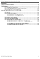
ECI-B14Fx Network Bullet Camera Quick Start Guide Contents 1 Appearance Description ......................................................................... 7 2 Installation ............................................................................................. 7 2.1 Ceiling/Wall Mounting.................................................................... 8 2.2 Ceiling/Wall Mounting with Junction Box .................................... 10 2.3 Waterproof Jacket Installation.........................
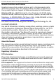
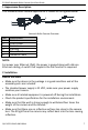
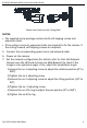
ECI-B14Fx Network Bullet Camera Quick Start Guide 1 Appearance Description This network bullet camera appearance is shown as the figures below. DC12VIN 4 5 6 1 2 3 Network Bullet Camera Overview No. 1 2 3 4 5 6 Description Lens Front Cover Back Cover Fix Ring Power Cord Network Cable NOTE: For power over Ethernet (PoE), the power is passed along with data on Ethernet cabling. A switch that supports the PoE function is required.
ECI-B14Fx Network Bullet Camera Quick Start Guide 2.1 Ceiling/Wall Mounting Before You Start Both wall mounting and ceiling mounting are suitable for the bullet camera. Ceiling mounting will be taken as an example in this section. Use these ceiling mounting steps as a reference for wall mounting. 1. Paste the drill template (supplied) to the desired mounting position on the ceiling/wall. 2. Drill the screw holes in the ceiling/wall according to the supplied drill template.
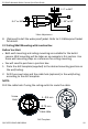
ECI-B14Fx Network Bullet Camera Quick Start Guide Mount the Camera to the Ceiling/Wall NOTES: The supplied screw package contains both self-tapping screws and expansion bolts. If the ceiling is cement, expansion bolts are required to fix the camera. If the ceiling is wood, self-tapping screws are required. 5. Connect the corresponding power cord, and network cable. 6. Power on the camera. 7.
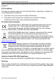
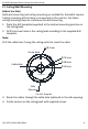
ECI-B14Fx Network Bullet Camera Quick Start Guide P: 0° to 360° 3 R: 0° to 360° T: -90° to 90° 2 1 3-Axis Adjustment 8. (Optional) Install the waterproof jacket. Refer to 2.3 Waterproof Jacket for details. 2.2 Ceiling/Wall Mounting with Junction Box Before You Start Both wall mounting and ceiling mounting are suitable for the bullet camera. Wall mounting will be taken as an example in this section. Use these wall mounting steps as a reference for ceiling mounting.
ECI-B14Fx Network Bullet Camera Quick Start Guide 3. Take apart the junction box, and align the screw holes of the bullet camera with those on the junction box’ cover. 4. Fix the camera on the junction box’s cover with three PM4 × 10 screws. Junction Box Cover Mount Camera onto Junction Box Cover 5. Secure the junction box’s body on the wall with three supplied screws. Waterproof Cover Cable Gland Fasten the Junction Box to the Wall 6. Route the cables through the cable hole.
ECI-B14Fx Network Bullet Camera Quick Start Guide 7. Combine the junction box cover with its body with three screws on the junction box’s cover. Combine Junction Box’s Cover with its Body 8. Repeat steps 5 to 7 of 2.1 9. Ceiling/Wall Mounting to complete the installation. 2.3 Waterproof Jacket Installation It is recommended to use the waterproof jacket (supplied) when the camera is installed outdoors. 1. If the network cable has retracted, cut off the network cable plug. 2.
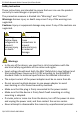
ECI-B14Fx Network Bullet Camera Quick Start Guide Network Interface O-ring Plug Waterproof Jacket Waterproof Ring Fix Nut Network Cable Waterproof Jacket Components Install Waterproof Jacket 3 Set the Network Camera over the LAN NOTE: You shall acknowledge that the use of the product with Internet access might be under network security risks. For avoidance of any network attacks and information leakage, please strengthen your own protection.
ECI-B14Fx Network Bullet Camera Quick Start Guide 3.2 Activate the Camera You must activate the camera first by setting a strong password for it before use. Activation via Web browser, SADP, and client software are all supported. We will take activation via SADP software and activation via Web browser as examples to introduce camera activation. NOTE: Refer to the of Network Camera user manual for activation via client software. 3.2.1 Activation via Web Browser 1. Power on the camera. 2.
ECI-B14Fx Network Bullet Camera Quick Start Guide 3.2.2 Activation via SADP Software SADP software is used for detecting the online device, activating the camera, and resetting the password. Get the SADP software from the supplied disk or the official Web site, and install it according to the prompts. Follow the steps to activate the camera. 1. Run the SADP software to search the online devices. 2. Check the device status on the device list, and select the inactive device. Select inactive device.
ECI-B14Fx Network Bullet Camera Quick Start Guide 5. You can enable the Hik-Connect service for the device during activation. Refer to Chapter 5.1 for detailed information. 6. Click Activate to start activation. 7. You can check whether the activation is complete on the pop-up window. If activation fails, make sure that the password meets the requirement and try again. 3.
ECI-B14Fx Network Bullet Camera Quick Start Guide NOTE: You can enable the Hik-Connect service for the device during activation. Refer to Chapter 5.1 for detailed information. 1. Input the admin password and click Modify to activate your IP address modification. 2. Batch IP address modification is supported by the SADP. Refer to the SADP user manual for details. 3.4 Access via Web Browser System Requirement: Operating System: Microsoft Windows XP SP1 and above version CPU: 2.
ECI-B14Fx Network Bullet Camera Quick Start Guide Login Interface 5. Install the plug-in before viewing the live video and managing the camera. Follow the installation prompts to install the plug-in. NOTE: You may have to close the Web browser to finish installing the plug-in. Download Plug-in 6. Reopen the Web browser after installing the plug-in and repeat steps 2 to 4 to login. NOTE: For further configuration instructions, see the network camera user manual. 3.
ECI-B14Fx Network Bullet Camera Quick Start Guide 3) Create or change the verification code. Verification Code Setting (SADP) NOTE: The verification code is required when adding the camera to Hik-Connect. 2. Click and read the “Terms of Service” and “Privacy Policy.” 3. Confirm the settings. 3.5.5 Enable Hik-Connect via a Web Browser Before You Start Activate the camera before enabling the service. Refer to Chapter 3.2. for more information. 1. Access the camera via a Web browser. Refer to Chapter 4. 2.
ECI-B14Fx Network Bullet Camera Quick Start Guide Platform Access Configuration (Web) 3. Set the Platform Access Mode to Hik-Connect. 4. Check the Enable checkbox. 5. Click and read the “Terms of Service” and “Privacy Policy” in the pop-up window. 6. Create or change the verification code for the camera. NOTE: A verification code is required when adding the camera to Hik-Connect. 7. Save the settings. 3.5.
ECI-B14Fx Network Bullet Camera Quick Start Guide Connect a Router NOTE: After the camera connects to the network, wait one minute before using the camera with Hik-Connect. 2. Add the camera to the Hik-Connect app: • If Accessing the Camera through an NVR: Tap “+” on the upper-right corner and scan the QR code that appears in the NVR interface. • If Accessing the Camera through a Web Browser: Tap the icon and type in the camera’s serial number. 3. Input your camera’s verification code.