
How to Guide

Title:
How to Connect the Cables of Alarm Input& Output
Of MVR
Version:
v1.0
Date:
8/8/2019
Product:
MVR
Page:
2 of 3
© Hangzhou Hikvision Digital Technology Co.,Ltd. All Rights Reserved.
No.555 Qianmo Road, Binjiang District, Hangzhou 310052, China • Tel: +86-571-8807-5998 • Fax: +1 909-595-0788
E-Mail: support@hikvision.com • www.hikvision.com
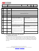
4
5
ALARM
5
TURN LEFT
Turn left signal input
6
ALARM
6
TURN
RIGHT
Turn right signal input
7
ALARM
7
ROLL
BACK
Roll back signal input
8
ALARM
8
PULSE
Reserved pulse signal input
9
12V
12V
12V Power supply
10
GND
GND
GND
11
A1
ALARM_OU
T1
single-pole double-throw switch
Default switch status of MDVR:
Normal Open (between Line 11 and Line
12),
Normal Closed (between Line 12 and
Line13)
OR
Normal Closed(between Line 11 and Line
12),
Normal Open(between Line 12 and Line13)
single-pole single-throw switch
Default switch status :
Normal Open (between Line 11 and Line 12),
OR
Normal Closed (between Line 11 and Line12)
12
B1
ALARM_OU
T1#
13
C1
ALARM_IN
4
Alarm input
14
A2
ALARM_OU
T2
single-pole double-throw switch
Default switch status of MDVR:
Normal Closed (between Line 14 and Line
15),
Normal Open (between Line 15 and Line16)
OR
Normal Open (between Line 14 and Line
15),
Normal Closed (between Line 15 and
Line16)
single-pole single-throw switch
Default switch status :
Normal Open (between Line 14 and Line 15),
OR
Normal Closed (between Line 14 and Line15)
15
B2
ALARM_OU
T2#
16
C2
Button
Button Alarm
2. Alarm Input & Alarm output cable connection
1) Alarm Input cable Connection:
MVR (mobile video recorder) adopts the high/low-level electrical signals (high level triggering
voltage: 6 to 36 VDC; low level triggering voltage: 0 to 5 VDC) to trigger an alarm input. In order
to avoid error report caused by voltage fluctuation, no alarm will be triggered by voltage ranging of
5 to 6 VDC. Customer can configure the Alarm Type to be NC or NO according to the alarm input
signal type;