
User Manual
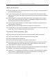
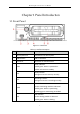
Table Of Contents
- Chapter 1 Panel Introduction
- Chapter 2 Installation and Connections
- Chapter 3 Start Up Device
- Chapter 4 Network
- Chapter 5 IP Camera
- Chapter 6 Camera Management
- Chapter 7 Live View
- Chapter 8 Storage
- Chapter 9 Playback
- Chapter 10 Platform
- Chapter 11 Backup
- Chapter 12 Events and Alarms
- 12.1 Configure Motion Detection Alarm
- 12.2 Configure Alarm Input
- 12.3 Configure Alarm Output
- 12.4 Configure Alarm Terminal
- 12.5 Configure Video Loss Alarm
- 12.6 Configure Video Tampering Alarm
- 12.7 Configure Video Quality Diagnostics
- 12.8 Configure Exception Alarm
- 12.9 Configure Satellite Positioning
- 12.10 Configure G-Sensor Alarm
- 12.11 Configure Arming Schedule and Linkage Actions
- 12.12 Configure Detection Area
- Chapter 13 User Account Management
- Chapter 14 General System Configuration
- Chapter 15 Maintenance
- Chapter 16 Shut Down Device
- Chapter 17 Appendix

Mobile Digital Video Recorder User Manual
8
Chapter 1 Panel Introduction
1.1 Front Panel
Figure 1-1 Front Panel
Table 1-1 Interface Descrption
No.
Name
Description
1
Dummy HDD lock
Lock/Unlock the dummy HDD.
2
USB interface
USB 2.0 interface.
3
IR receiver
IR receiver for remote control.
4
PWR
Power indicator
Solid green: Device is powered on.
Solid red: Device is standby.
RDY
Ready indicator
Solid green: Device starts up normally.
REC
Recording indicator
Solid green: Device is recording normally.
GNSS
GNSS indicator
Unlit: Positioning module is abnormal.
Solid green: Device is positioning.
Flashing green: Positioning succeeded.
ANT
ANT indicator
Unlit: Dialing module is abnormal.
Solid green: Device is dialing.