
User Manual
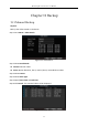
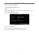
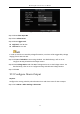
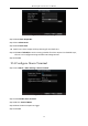
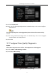
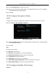
Table Of Contents
- Chapter 1 Panel Introduction
- Chapter 2 Installation and Connections
- Chapter 3 Start Up Device
- Chapter 4 Network
- Chapter 5 IP Camera
- Chapter 6 Camera Management
- Chapter 7 Live View
- Chapter 8 Storage
- Chapter 9 Playback
- Chapter 10 Platform
- Chapter 11 Backup
- Chapter 12 Events and Alarms
- 12.1 Configure Motion Detection Alarm
- 12.2 Configure Alarm Input
- 12.3 Configure Alarm Output
- 12.4 Configure Alarm Terminal
- 12.5 Configure Video Loss Alarm
- 12.6 Configure Video Tampering Alarm
- 12.7 Configure Video Quality Diagnostics
- 12.8 Configure Exception Alarm
- 12.9 Configure Satellite Positioning
- 12.10 Configure G-Sensor Alarm
- 12.11 Configure Arming Schedule and Linkage Actions
- 12.12 Configure Detection Area
- Chapter 13 User Account Management
- Chapter 14 General System Configuration
- Chapter 15 Maintenance
- Chapter 16 Shut Down Device
- Chapter 17 Appendix

Mobile Digital Video Recorder User Manual
55
Figure 12-2 Alarm Input Settings
Step 2 Select Alarm Input No.
Step 3 Enter Alarm Name.
Step 4 Select Trigger Level.
High level: 6 to 36 VDC.
Low level: 0 to 5 VDC
In order to avoid error caused by voltage fluctuation, no alarm will be triggered by voltage
ranging from 5 VDC to 6 VDC.
Step 5 Click Set of Schedule to set arming schedule. For detailed steps, refer to 12.11
Configure Arming Schedule and Linkage Actions.
Step 6 Check Linkage Action and click Set of Linkage Action to set the linkage actions. For
detailed steps, refer to 12.11 Configure Arming Schedule and Linkage Actions.
Step 7 Click OK.
12.3 Configure Alarm Output
Purpose:
Configure the arming schedule, alarm duration time and alarm name for alarm output.
Step 1 Go to Menu > Other Settings > Alarm Out.