
User Manual

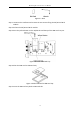
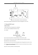
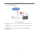
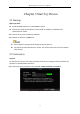
Table Of Contents
- Chapter 1 Panel Introduction
- Chapter 2 Installation and Connections
- Chapter 3 Start Up Device
- Chapter 4 Network
- Chapter 5 IP Camera
- Chapter 6 Camera Management
- Chapter 7 Live View
- Chapter 8 Storage
- Chapter 9 Playback
- Chapter 10 Platform
- Chapter 11 Backup
- Chapter 12 Events and Alarms
- 12.1 Configure Motion Detection Alarm
- 12.2 Configure Alarm Input
- 12.3 Configure Alarm Output
- 12.4 Configure Alarm Terminal
- 12.5 Configure Video Loss Alarm
- 12.6 Configure Video Tampering Alarm
- 12.7 Configure Video Quality Diagnostics
- 12.8 Configure Exception Alarm
- 12.9 Configure Satellite Positioning
- 12.10 Configure G-Sensor Alarm
- 12.11 Configure Arming Schedule and Linkage Actions
- 12.12 Configure Detection Area
- Chapter 13 User Account Management
- Chapter 14 General System Configuration
- Chapter 15 Maintenance
- Chapter 16 Shut Down Device
- Chapter 17 Appendix

Mobile Digital Video Recorder User Manual
17
Please contact the vehicle manufacturer for the connection information of starting
switch.
The vehicle ignition switch, also called car key, controls the startup and shutdown of
the vehicle. Most of vehicles adopt positive pole ignition switch currently.
Figure 2-14 Connection of Positive Pole Ignition Switch
Ignition switch is connected to the positive pole of +12/24 VDC of vehicle batteries. Make
sure that the connection is correct, and then perform the following steps:
Step 1 Connect the "DC IN +" of the device to the positive pole of vehicle batteries, jumping
over the switch of normal vehicle power.
Step 2 Connect the "DC IN -" of the device to the negative pole of vehicle batteries.
Step 3 Connect the "ACC" of the device to the vehicle ignition switch.
Step 4 The normal vehicle power refers to the main power of the vehicle power supply
system. After the vehicle is off, the normal vehicle power still provides direct-current
source for the other devices inside and generally a main switch is used to turn on/off
it.