
User Manual

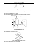
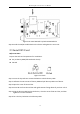
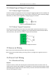
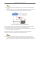
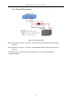
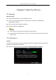
Table Of Contents
- Chapter 1 Panel Introduction
- Chapter 2 Installation and Connections
- Chapter 3 Start Up Device
- Chapter 4 Network
- Chapter 5 IP Camera
- Chapter 6 Camera Management
- Chapter 7 Live View
- Chapter 8 Storage
- Chapter 9 Playback
- Chapter 10 Platform
- Chapter 11 Backup
- Chapter 12 Events and Alarms
- 12.1 Configure Motion Detection Alarm
- 12.2 Configure Alarm Input
- 12.3 Configure Alarm Output
- 12.4 Configure Alarm Terminal
- 12.5 Configure Video Loss Alarm
- 12.6 Configure Video Tampering Alarm
- 12.7 Configure Video Quality Diagnostics
- 12.8 Configure Exception Alarm
- 12.9 Configure Satellite Positioning
- 12.10 Configure G-Sensor Alarm
- 12.11 Configure Arming Schedule and Linkage Actions
- 12.12 Configure Detection Area
- Chapter 13 User Account Management
- Chapter 14 General System Configuration
- Chapter 15 Maintenance
- Chapter 16 Shut Down Device
- Chapter 17 Appendix

Mobile Digital Video Recorder User Manual
16
2.4 Alarm Input/Output Connection
2.4.1 Alarm Input Connection
The device adopts the high/low-level electrical signals triggering (high level: 6 to 36 VDC; low
level: 0 to 5 VDC) to realize alarm input. And in order to avoid error report caused by voltage
fluctuation, no alarm will be triggered by voltage ranging of 5 to 6VDC.
Figure 2-12 Alarm Input Connection
2.4.2 Alarm Output Connection
The alarm output interfaces A1 and B1 of the mobile DVR is opened normally if no alarm
occurs. When an alarm output is triggered, the corresponding A1 and B1 interfaces will be
connected. Thus, the active alarm device is required for the system.
DC
Figure 2-13 Alarm Output Connection
2.5 Sensor-in Wiring
Step 1 Connect the delivered extension cable to I/O interface.
Step 2 Connect the vehicle braking, reversing, left-turn, and right-turn signals to sensor-in
interface.
2.6 Power Cord Wiring
2.6.1 Shutdown Delay
Purpose:
The device starts up when the vehicle ignites and shuts down after the vehicle is off. The
vehicle ignition startup and shutdown are realized by the vehicle positive pole ignition switch
(providing high level signal when the switch closes). The wire connection of the device varies
with the vehicle ignition models.