Mobile Digital Video Recorder User Manual Mobile DVR User Manual 0
Mobile Digital Video Recorder User Manual TABLE OF CONTENTS Chapter 1 Panel Introduction .................................................................................................................................................. 8 1.1 Front Panel ................................................................................................................................................................... 8 1.2 Rear Panel ............................................................................
Mobile Digital Video Recorder User Manual 7.3 Right-Click Menu ....................................................................................................................................................... 38 7.4 PTZ Operation ............................................................................................................................................................ 39 7.4.1 Configure PTZ Settings ......................................................................................
Mobile Digital Video Recorder User Manual 14.1 Configure Basic Display Settings ............................................................................................................................. 65 14.2 Configure DST Settings............................................................................................................................................ 65 14.3 Configure NTP ................................................................................................................
Mobile Digital Video Recorder User Manual User Manual COPYRIGHT ©2017 Hangzhou Hikvision Digital Technology Co., Ltd. ALL RIGHTS RESERVED. Any and all information, including, among others, wordings, pictures, graphs are the properties of Hangzhou Hikvision Digital Technology Co., Ltd. or its subsidiaries (hereinafter referred to be “Hikvision”).
Mobile Digital Video Recorder User Manual Regulatory Information FCC Information Please take attention that changes or modification not expressly approved by the party responsible for compliance could void the user’s authority to operate the equipment. FCC compliance: This equipment has been tested and found to comply with the limits for a Class A digital device, pursuant to part 15 of the FCC Rules.
Mobile Digital Video Recorder User Manual Applicable Models This manual is applicable to the models listed in the following table. Series Model DS-M5504HM-T(1T) DS-M5504HM-T DS- M5504HM-T/GW(1T) DS- M5504HM-T/GW/WI58(1T) Symbol Conventions The symbols that may be found in this document are defined as follows. Symbol Description Provides additional information to emphasize or supplement important points of the main text.
Mobile Digital Video Recorder User Manual Safety Instructions Proper configuration of all passwords and other security settings is the responsibility of the installer and/or end-user. In the use of the product, you must be in strict compliance with the electrical safety regulations of the nation and region. Please refer to technical specifications for detailed information.
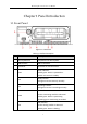
Mobile Digital Video Recorder User Manual Chapter 1 Panel Introduction 1.1 Front Panel Figure 1-1 Front Panel Table 1-1 Interface Descrption No. Name Description 1 Dummy HDD lock Lock/Unlock the dummy HDD. 2 USB interface USB 2.0 interface. 3 IR receiver IR receiver for remote control. 4 Power indicator PWR Solid green: Device is powered on. Solid red: Device is standby. RDY REC Ready indicator Solid green: Device starts up normally.
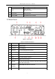
Mobile Digital Video Recorder User Manual Flashing green: Dialing up succeeded. ALM Alarm indicator Red: Alarm occurs. 5 SD card slot Slot for SD card. 6 Dummy HDD Two HDDs can be installed. 1.2 Rear Panel Figure 1-2 Rear Panel Table 1-2 Interface Descrption No. Name Description 1 CH1 to CH4 4 video inputs. 2 RS-232-1 For debugging. 3 RS-232-2 For connecting external devices. 4 USB interface USB interface of 5-pin aviation plug. 5 Power 6-pin aviation plug for power supply.
Mobile Digital Video Recorder User Manual 11 AUX Auxiliary Wi-Fi antenna interface. 12 Wi-Fi antenna Wi-Fi antenna interface.
Mobile Digital Video Recorder User Manual Chapter 2 Installation and Connections Product pictures in following chapters are for reference only. In the event of any conflicts between this manual and the product, the later prevails. 2.1 Install HDD Before You Start: Prepare the tools and components for installation: One factory recommended 2.5-inch HDD.
Mobile Digital Video Recorder User Manual Figure 2-2 Take Apart Dummy HDD Step 4 Place HDD into the dummy HDD, with the PCB facing down. Figure 2-3 Place HDD Step 5 Push the HDD along the direction shown in Figure 2-4 to connect HDD with socket of dummy HDD. Figure 2-4 Push HDD Step 6 Use four sunk screws to fix HDD with dummy HDD.
Mobile Digital Video Recorder User Manual Figure 2-5 Fix HDD Step 7 Reassemble the dummy HDD. Figure 2-6 Reassemble Dummy HDD Step 8 Plug the dummy HDD back to the device and then tighten the screws clockwise. Step 9 Turn the key clockwise to lock dummy HDD. 2.2 Install SIM Card Purpose: Pluggable 3G/4G wireless communication module is designed for the device and you should install the SIM card to realize the wireless communication function.
Mobile Digital Video Recorder User Manual Figure 2-7 Tools Step 1 Use wrench to unfasten and remove the two screws fixing the 3G/4G and Wi-Fi module. Step 2 Pull out the 3G/4G and Wi-Fi module. Step 3 Press the yellow button on the 3G/4G slot and then pull the SIM card tray out. Figure 2-8 Pull out SIM Card Tray Step 4 Place the SIM card on SIM card tray. Figure 2-9 Place SIM card on SIM Card Tray Step 5 Insert the SIM card tray back to SIM card slot.
Mobile Digital Video Recorder User Manual Figure 2-10 Insert SIM Card Tray back to SIM Card Slot Step 6 Install the 3G/4G module back to the device and tighten the set screw. 2.3 Install SD Card Before You Start Prepare the tools and components for installation: Key to dummy HDD (delivered with device) SD card Figure 2-11 Tools Step 1 Insert the key and turn counterclockwise to unlock dummy HDD. Step 2 Unfasten the two screws of dummy HDD and pull dummy HDD out of device.
Mobile Digital Video Recorder User Manual 2.4 Alarm Input/Output Connection 2.4.1 Alarm Input Connection The device adopts the high/low-level electrical signals triggering (high level: 6 to 36 VDC; low level: 0 to 5 VDC) to realize alarm input. And in order to avoid error report caused by voltage fluctuation, no alarm will be triggered by voltage ranging of 5 to 6VDC. Figure 2-12 Alarm Input Connection 2.4.
Mobile Digital Video Recorder User Manual Please contact the vehicle manufacturer for the connection information of starting switch. The vehicle ignition switch, also called car key, controls the startup and shutdown of the vehicle. Most of vehicles adopt positive pole ignition switch currently. Figure 2-14 Connection of Positive Pole Ignition Switch Ignition switch is connected to the positive pole of +12/24 VDC of vehicle batteries.
Mobile Digital Video Recorder User Manual 2.6.2 Timed Shutdown Figure 2-15 Timing On/Off Step 2 Connect the “DC IN +” and “KEY +” of mobile DVR to the positive pole of vehicle batteries. Step 3 Connect the “DC IN -” and “KEY -” of mobile DVR to the negative pole of vehicle batteries. For detailed time settings of time-delay shutdown, see 16.1 Enable Scheduled Startup/Shutdown.
Mobile Digital Video Recorder User Manual Chapter 3 Start Up Device 3.1 Startup Before you start: Install the HDD. Refer to 2.1 Install HDD for details. Connect the cables and modules correctly. Refer to Chapter 2 Installation and Connections for details. Step 1 Insert the key into the dummy HDD lock. Step 2 Rotate it clockwise to ON status. Do not perform any operations during the startup process. The startup process takes about 1 minute.
Mobile Digital Video Recorder User Manual STRONG PASSWORD RECOMMENDED–We highly recommend you create a strong password of your own choosing (Using a minimum of 8 characters, including at least three of the following categories: upper case letters, lower case letters, numbers, and special characters.) in order to increase the security of your product.
Mobile Digital Video Recorder User Manual Chapter 4 Network 4.1 Set Local Network Step 1 Go to Menu > Basic Settings > Network. Figure 4-1 Local Network Settings Step 2 Enter the device IP Address, Subnet Mask, Default Gateway, DNS Server Address, and Download Server IP. Step 3 Optionally, click Set of More Settings to enable/disable LAN Sharing. LAN Sharing: Enable the function to share 3G/4G network to network interface.
Mobile Digital Video Recorder User Manual Figure 4-2 Dialing Settings Step 2 Check Enable Dialing. Step 3 Configure the 3G/4G VPDN (Virtual Private Dialup Network) settings. Please consult the local operator for the network parameters of the VPDN. 1) 2) 3) 4) 5) Click the Set button of More Settings. Select Bearing Mode. Enter APN (Access Point Name), Dial Number, User Name, and Password. Select the Verification Protocol. Click OK.
Mobile Digital Video Recorder User Manual Figure 4-4 Wi-Fi Settings Step 2 Check Enable WiFi. Step 3 Select the Configuration file. 5 configuration files are available and only one SSID can be set for each file. Step 4 Select network SSID (Service Set Identifier), Security Type, Encryption Type, and Key. Step 5 Set the IP address and DNS server for Wi-Fi network. 6) Click Set of More Settings. 7) Configure IP address and DNS parameters. 8) Click OK. Figure 4-5 IP & DNS Settings for Wi-Fi Step 6 Click OK.
Mobile Digital Video Recorder User Manual Figure 4-6 Wi-Fi Status Interface 4.2.3 Set Wi-Fi AP Purpose: Configure Wi-Fi access point settings. Step 1 Go to Menu > Basic Settings > WiFi. Figure 4-7 Wi-Fi Settings Step 2 Click Set of WiFi AP Figure 4-8 Wi-Fi Access Point Settings Step 3 Check Enable WiFi AP and edit other parameters as required.
Mobile Digital Video Recorder User Manual Enable WiFi AP: Once enabled, the device can work as a wireless router. Enable WiFi Broadcast: Once enabled, other devices are able to detect the SSID of the device. Enable WiFi Hotspot: Enable it to share the device’s internet connection. Other devices can access to internet via joining the hotspot. Step 4 Click OK. 4.
Mobile Digital Video Recorder User Manual Figure 4-10 Add IP Address Step result: The trusted IP address will be added on the white list. The configured whitelist will be cleared after you reboot the device.
Mobile Digital Video Recorder User Manual Chapter 5 IP Camera Purpose: Add IP cameras to the device. You can get the live view, record the video, and set the parameters of the connected IP camera. 5.1 Activate IP Cameras Purpose: Before adding an IP camera, activate it by setting a password for it. Step 1 Go to Menu > Other Settings > IPC Settings. Figure 5-1 IPC Settings Step 2 Select an inactivated IP camera. Step 3 Activate the selected IP camera. Option 1: Quick Activation Click Quickly Activate.
Mobile Digital Video Recorder User Manual Figure 5-2 Activate IP Camera Manually 2) Enter New Password and enter the same password in Confirm. STRONG PASSWORD RECOMMENDED – We highly recommend you create a strong password of your own choosing (Using a minimum of 8 characters, including at least three of the following categories: upper case letters, lower case letters, numbers, and special characters.) in order to increase the security of your product.
Mobile Digital Video Recorder User Manual Step 3 Click Quickly Add. Figure 5-3 Quick Add IP Camera : The IP camera is disconnected. : The IP camera is connected. 5.2.2 Add IP Camera Manually Step 1 Go to Menu > Other Settings > IPC Settings. Step 2 Click Manually Add. Step 3 Select the IP channel No. for the IP camera. Step 4 Edit the required information, including the IP address, Protocol, Port No., User Name, and Password. Step 5 Click OK. Figure 5-4 Manual Add 5.2.
Mobile Digital Video Recorder User Manual Step 1 Go to Menu > Other Settings > IPC Settings. Step 2 Click Manually Add. Step 3 Click Protocol. Figure 5-5 Protocol Step 4 Edit parameters as required. Step 5 Click OK 5.3 Edit IP Cameras Step 1 Select an added IP camera and click Edit. Step 2 Edit the parameters. Step 3 Enter Password. The password must be correct. Step 4 Click OK. Figure 5-6 Edit IP Camera 5.4 Delet IP Cameras Step 1 Select an IP camera and click Delete.
Mobile Digital Video Recorder User Manual Figure 5-7 Delete IP Camera 31
Mobile Digital Video Recorder User Manual Chapter 6 Camera Management 6.1 Basic Image Settings 6.1.1 Set OSD Parameters Purpose: Configure the camera name, OSD (On Screen Display) settings, etc. Step 1 Go to Menu > Other Settings > Camera. Figure 6-1 Camera Settings Step 2 Select the Camera from the drop-down list. Step 3 Edit parameters as your desire. Step 4 Optionally, select the camera in Copy to dropdown list and click Copy to copy the current settings to the selected camera. Step 5 Click OK. 6.1.
Mobile Digital Video Recorder User Manual Figure 6-2 Camera Settings Step 2 Click Set of More Setting. Figure 6-3 More Setting Step 3 Click Set of Image Settings. Figure 6-4 Image Settings Step 4 Edit the parameters. Step 5 Click OK. Step 6 Click OK in advanced settings interface. Step 7 Click OK in camera settings interface. 6.1.3 Set TVI Camera Purpose: Configure the image parameters of connected TVI camera. The feature is only available for TVI camera.
Mobile Digital Video Recorder User Manual Step 1 Go to Menu > Other Settings > Camera. Figure 6-5 Advanced Settings Step 2 Click Set of More Setting. Step 3 Click Set of TVI Camera Settings. Figure 6-6 TVI Camera Settings Step 4 Edit the parameters according to your needs. Step 5 Click OK in TVI Camera Settings interface. Step 6 Click OK in Advanced settings interface. Step 7 Click OK in Camera settings interface. 6.
Mobile Digital Video Recorder User Manual Figure 6-7 Advanced Settings Step 2 Click Set of More Setting. Step 3 Check Private Mask. Step 4 Click Area Settings of Private Mask. Step 5 Draw areas. Step 6 Right click and select Exit. Step 7 Click OK in Advanced settings interface. Step 8 Click OK in Camera settings interface. 6.3 Set Mirror Type Purpose: Set the mirror type of the image as left/right, up/down, or center. The camera image will change according to the selected mirror type.
Mobile Digital Video Recorder User Manual Figure 6-8 Advanced Settings Step 2 Click Set of More Setting. Step 3 Select Mirror Type as required. Step 4 Click OK in Advanced settings interface. Step 5 Click OK in Camera settings interface.
Mobile Digital Video Recorder User Manual Chapter 7 Live View 7.1 Preview Settings Purpose: Configure the dwell time of live view, set the camera order, enable/disable the audio preview, etc. Step 1 Go to Menu > Other Settings > Preview. Figure 7-1 Preview Settings Step 2 Select the Video Output according to the actual needs. Step 3 Configure the Preview Mode, Dwell Time, Enable Audio Output. Preview Mode: Select the window division mode for live view.
Mobile Digital Video Recorder User Manual Figure 7-2 Preview Settings Step 2 Click Set of Camera Order. Step 3 Click / to switch camera. Step 4 Click OK. Figure 7-3 Camera Order Step 5 Click OK in Preview Settings interface. 7.3 Right-Click Menu Purpose: In live view, right click on a camera to pop up right-click menu.
Mobile Digital Video Recorder User Manual Table 7-1 Item Description Item Description Menu Enter the main menu of the system by right clicking the mouse. Multi-Screen Adjust the screen layout by choosing from the dropdown list. Next Screen Switch to the next screen. Playback Enter the playback interface and start playing back the video of the selected channel immediately. PTZ Click to pop up PTZ control panel. 7.4 PTZ Operation 7.4.
Mobile Digital Video Recorder User Manual 7.4.2 PTZ Control Panel In live view interface, right click a PTZ camera and click PTZ on right-click menu.
Mobile Digital Video Recorder User Manual Chapter 8 Storage 8.1 Storage Settings 8.1.1 Format HDD Purpose: A newly installed hard disk drive (HDD) must be initialized before it can be used. Step 1 Go to Menu > Storage. Figure 8-1 Storage Management Step 2 Check the HDD to format. Step 3 Click Format. 8.1.2 Configure Overwrite Purpose: The overwrite function is enabled by default. If the function is disabled, the recording will stop when the storage device is full. Step 1 Go to Menu > Storage.
Mobile Digital Video Recorder User Manual Figure 8-2 Storage Management Step 2 Select Overwrite as Yes or No. Step 3 Click OK. 8.1.3 View S.M.A.R.T. Information Purpose: The S.M.A.R.T. (Self-Monitoring, Analysis and Reporting Technology) is a monitoring system for HDD to detect and report on various indicators of reliability in the hopes of anticipating failures. Step 1 Go to Menu > Storage. Figure 8-3 Storage Management Step 2 Select an HDD. Step 3 Click S.M.A.R.T. Info.
Mobile Digital Video Recorder User Manual Figure 8-4 S.M.A.R.T Information 8.2 Recording Settings 8.2.1 Configure Record Settings Purpose: Configure the transmission stream type, the resolution, frame rate, etc. Step 1 Go to Menu > Basic Settings > Record. Figure 8-5 Record Settings Step 2 Select camera in Camera drop-down list. Step 3 Configure the image parameters. Encoding Parameters Main Stream (Normal): Used for continuous recording. Main Stream (Event): Used for event recording.
Mobile Digital Video Recorder User Manual Variable and Constant are selectable. Variable: The video quality is configurable. Constant: The video quality is set as Medium and cannot be edited. Video Quality Bitrate type is variable, you can set the video quality as Highest, Higher, Medium, Low, Lower, or Lowest. Frame Rate Frame rate refers to the frequency of the image frame after compression.
Mobile Digital Video Recorder User Manual Step 3 Check Motion Detection. Step 4 Click Area Settings of Motion Detection. Step 5 Edit area settings. For details, refer to 12.12 Configure Detection Area. Step 6 Click OK. Step 7 Set motion detection recording schedule. For details, refer to 8.2.5 Configure Schedule. Recording type should be alarm, motion|alarm, or motion&alarm. 8.2.3 Configure Alarm Triggered Recording Purpose: Follow the procedure to configure alarm triggered recording.
Mobile Digital Video Recorder User Manual Figure 8-8 Alarm Terminal Step 2 Check Enable Alarm Terminal. Step 3 Edit the terminal name in Terminal Name text field. Step 4 Select Set of Trigger Record Channel to set alarm triggered recording channel(s). Step 5 Click OK. 8.2.5 Configure Schedule Step 1 Go to Menu > Basic Settings > Record. Step 2 Click Set of Schedule. Step 3 Check Enable Schedule. Step 4 Select the day from the dropdown list for settings.
Mobile Digital Video Recorder User Manual Figure 8-9 Record Schedule Settings 8.3 Sensor-in Settings Purpose: Sensor-in detects and records the driving information of the vehicle, including pedal braking, turning left/right, reversing, etc. Step 1 Go to Menu > Basic Settings > Sensor-In. Figure 8-10 Sensor-In Settings Step 2 Set Triggering Level and Full Screen Monitoring for sensor-in. Step 3 Click OK.
Mobile Digital Video Recorder User Manual Chapter 9 Playback 9.1 Instant Playback Purpose: You can search and play back the record files stored on the device instantly. Step 1 Go to Menu > Video Search. Figure 9-1 Video Search Step 2 Select Search Mode as General. Only general videos support instant playback. General: Normal videos Step 3 Select Camera. Step 4 Select Video Type. Step 5 Specify Start Time and End Time. Step 6 Click Play to play back the matched videos.
Mobile Digital Video Recorder User Manual Figure 9-2 Video Search Step 2 Select Search Mode. General: Normal videos Event: Motion detection, alarm, motion│alarm, motion&alarm videos. Step 3 Select Camera. Step 4 Select Video Type. Step 5 Specify Start Time and End Time. Step 6 Click Search. The matched videos will be displayed. Figure 9-3 Search Result Step 7 Select a video and click Play.
Mobile Digital Video Recorder User Manual Chapter 10 Platform 10.1 Ehome Purpose: The device can be remotely accessed via Ehome platform. Before you start: Create the device ID on the Ehome platform. Step 1 Go to Menu > Basic Settings > Platform. Figure 10-1 Platform Settings Step 2 Check Platform Enable. Step 3 Select Platform as Ehome. Step 4 Configure the following parameters. Server IP: Enter the static IP address of iVMS server. Port No.: The default value is 7660.
Mobile Digital Video Recorder User Manual Register the device in guarding vision platform. For detailed steps, refer to 10.3 Register Device in Guarding Vision platform. Step 1 Go to Menu > Basic Settings > Platform. Step 1 Check Enable Platform. Step 2 Select Platform as Guarding Vision. Step 3 Click OK and reboot the device to activate the new settings. Step 4 Optionally, go to Menu > Status > Platform to view the platform status. 10.
Mobile Digital Video Recorder User Manual Chapter 11 Backup 11.1 Manual Backup Purpose: Back up the videos stored on the device. Step 1 Go to Menu > Video Search. Figure 11-1 Video Search Step 2 Select Search Mode. General: Normal videos Event: Motion detection, alarm, motion│alarm, motion&alarm videos. Step 3 Select Camera. Step 4 Select Video Type. Step 5 Specify Start Time and End Time. Step 6 Click Search. The matched videos will be displayed.
Mobile Digital Video Recorder User Manual Step 7 Select the videos and click Export. 11.2 Format Backup Device Purpose: View the status and the free space/capacity of the connected backup device. And you can also format the backup device. Step 1 Go to Menu > Maintenance > Storage. Figure 11-3 Backup Device Step 2 Select the Backup Device. Step 3 View the Status and Free Space/Capacity of the backup device. Step 4 Optionally, click Format to format the selected backup device.
Mobile Digital Video Recorder User Manual Chapter 12 Events and Alarms 12.1 Configure Motion Detection Alarm Purpose: When motion detection alarm is configured, once a motion event is detected, the device starts to record and multiple linkage actions will be triggered. Step 1 Go to Menu > Other Settings > Camera. Step 2 Click Set of More Setting. Figure 12-1 Motion Detection Settings Step 3 Check Motion Detection to enable the function. Step 4 Set the area for motion detection.
Mobile Digital Video Recorder User Manual Figure 12-2 Alarm Input Settings Step 2 Select Alarm Input No. Step 3 Enter Alarm Name. Step 4 Select Trigger Level. High level: 6 to 36 VDC. Low level: 0 to 5 VDC In order to avoid error caused by voltage fluctuation, no alarm will be triggered by voltage ranging from 5 VDC to 6 VDC. Step 5 Click Set of Schedule to set arming schedule. For detailed steps, refer to 12.11 Configure Arming Schedule and Linkage Actions.
Mobile Digital Video Recorder User Manual Figure 12-3 Alarm Output Settings Step 2 Select Alarm Output No. Step 3 Enter Alarm Name. Step 4 Select Dwell Time. Dwell Time: Alarm output will keep alarming for the dwell time. Step 5 Click Set of Schedule to set the arming schedule for alarm outputs. For detailed steps, refer to 12.11 Configure Arming Schedule and Linkage Actions. Step 6 Click OK. 12.4 Configure Alarm Terminal Step 1 Go to Menu > Other Settings > Alarm Terminal.
Mobile Digital Video Recorder User Manual 12.5 Configure Video Loss Alarm Purpose: When the device cannot receive video signal from the front-end devices, the video loss alarm will be triggered. Linkage actions, including audible warning and alarm output, can be set to respond. Step 1 Go to Menu > Other Settings > Camera. Step 2 Click Set of More Setting. Figure 12-5 Video Loss Step 3 Check Video Loss. Step 4 Set arming schedule and linkage actions. For detailed steps, refer to 12.
Mobile Digital Video Recorder User Manual Figure 12-6 Video-Tampering Step 3 Check Tamper-proof. Step 4 Set area for video tampering detection. For detailed steps, refer to 12.12 Configure Detection Area. The video tampering alarm can be triggered only when the view of the camera is fully covered. Step 5 Set arming schedule and linkage actions. For detailed steps, refer to 12.11 Configure Arming Schedule and Linkage Actions. Step 6 Click OK. 12.
Mobile Digital Video Recorder User Manual Step 3 Check Video Quality to enable the function. Step 4 Set arming schedule and linkage actions. For detailed steps, refer to 12.11 Configure Arming Schedule and Linkage Actions. Step 5 Click OK. 12.8 Configure Exception Alarm Purpose: Configure alarms which are triggered by exceptions to take necessary actions in time. Step 1 Go to Menu > Other Settings > Exception.
Mobile Digital Video Recorder User Manual The built-in GNSS module supports GPS (Global Positioning System), enabling device positioning and speed limit alarm. Step 1 Go to Menu > Basic Settings > Position. Figure 12-9 Position Step 2 Select Positioning Module. RS-232: Obtain data from the satellite positioning module connected through RS-232 interface. RS-485: Obtain data from the satellite positioning module connected through RS-485 interface.
Mobile Digital Video Recorder User Manual Step 1 Go to Menu > Basic Settings > G-Sensor. Figure 12-10 G-Sensor Settings Step 2 Select you G-sensor mode under Module: RS-232: The G-sensor is connected to the mobile DVR through RS-232 interface. Built-in: The G-sensor is built in the mobile DVR. Step 3 Set the limit value for acceleration alarm in X, Y and Z directions. X, Y and Z represent the direction of acceleration and the unit of alarm value is G (G=9.8 m/s2).
Mobile Digital Video Recorder User Manual Trigger an audible beep when an alarm is detected. Trigger Alarm Output Trigger an alarm output when an alarm is detected. Step 6 Click OK. Figure 12-11 Linkage Action 12.12 Configure Detection Area Step 1 Click Area Settings. Step 2 Draw to draw detection area. Step 3 Optionally, right click to delete areas or set detection sensitivity. Step 4 Right click and select Exit.
Mobile Digital Video Recorder User Manual Chapter 13 User Account Management 13.1 Add User Purpose: Add and delete users, and modify the password and permission of users. Step 1 Go to Menu > Other Settings > User. Figure 13-1 User Management Step 2 Click Add. Figure 13-2 Add User Step 3 Enter User Name and Password and enter the same password in Confirm. Step 4 Select the user permission level. Operator: The operator has permissions for Preview, Playback, Backup, Log Search and Parameters Settings.
Mobile Digital Video Recorder User Manual 13.2 Delete User Step 1 Go to Menu > Other Settings > User. Step 2 Select a user and click Delete. Step 3 Click Yes in confirmation message box. 13.3 Edit User Step 1 Go to Menu > Other Settings > User. Step 2 Select a user and click Modify. Step 3 Edit parameters as required. Step 4 Click OK.
Mobile Digital Video Recorder User Manual Chapter 14 General System Configuration 14.1 Configure Basic Display Settings Purpose: Set system time, select CVBS output standard, enable password and configure DST settings, etc. Step 1 Go to Menu > Other Settings > Display. The system language is set as English by default and is not editable. Figure 14-1 Display Settings Step 2 Edit parameters as required. CVBS Output Standard: NTSC or PAL are selectable. Set it according to actual video input standard.
Mobile Digital Video Recorder User Manual Figure 14-2 DST Settings Step 3 Check Enable DST. Step 4 Set the start time and end time for DST. Step 5 Select DST bias. Step 6 Click OK in DST settings interface. Step 7 Click OK in Display Settings. 14.3 Configure NTP Step 1 Go to Menu > Basic Settings > Network. Figure 14-3 Local Network Settings Step 2 Click Set of NTP.
Mobile Digital Video Recorder User Manual Figure 14-4 NTP Settings Step 3 Check NTP to enable the function. Step 4 Enter Synchronization Interval. Step 5 Enter the IP address of NTP server. Step 6 Click OK in NTP settings interface. Step 7 Click OK in network settings interface. 14.4 Configure Advanced Display Settings Purpose: You can set the system time, select the CVBS output standard, enable the password, configure the DST settings, etc. Step 1 Go to Menu > Other Settings > Display.
Mobile Digital Video Recorder User Manual Device No.: Edit the device No. for remote control. The device No. ranges from 1 to 255. The default device No. is 255. It is not recommended to modify Device No. Otherwise, you need to enter the Device No. on the remote control every time you use it. CVBS Brightness: Adjust video output brightness. Menu Transparency: The transparency proportion of the menu displayed on the live view interface. You can set it as 1:3, 1:1, 3:1, or Non-transparent.
Mobile Digital Video Recorder User Manual Chapter 15 Maintenance 15.1 Check Status Go to Menu > Status to view status of recording, 3G/4G, platform, satellite positioning, G-Sensor, alarm, and WiFi. Figure 15-1 Status Interface 15.2 View System Information Go to Menu > Maintenance > Information to view the device name, model, serial No., firmware version, encoding version, and panel version. Figure 15-2 System Information 15.
Mobile Digital Video Recorder User Manual 15.3.1 Upgrade by Local USB Flash Disk Before you start: Connect the USB device that contains the upgrade firmware. The upgrade firmware should be stored in the root directory of the USB device. Step 1 Go to Menu > Maintenance > Upgrade. Step 2 Select Upgrade Type as USB Upgrade. Figure 15-3 Upgrade Interface Step 3 Click Upgrade to start upgrading and reboot the device to activate the new settings. 15.3.
Mobile Digital Video Recorder User Manual Figure 15-4 Upgrade Interface Step 2 Select Upgrade Type as FTP Upgrade. Step 3 Enter FTP Server Address. Step 4 Click Upgrade to start upgrading and reboot the device to activate the new settings. 15.4 Log Operation 15.4.1 View Log Files Purpose: The operation, alarm, exception and information of the device can be stored in log files, which can be viewed and exported at any time. Step 1 Go to Menu > Maintenance > Log Search.
Mobile Digital Video Recorder User Manual Figure 15-6 Log Search 15.4.2 Export Log Files Purpose: The operation, alarm, exception and information of the device can be stored in log files, which can be viewed and exported at any time. Before you start: Connect a backup device to the device. Step 1 Go to Menu > Maintenance > Log Search. Figure 15-7 Log Search Interface Step 2 Search log files. For detailed steps, refer to 15.4.1 View Log Files. Step 3 Click Export. 15.
Mobile Digital Video Recorder User Manual Figure 15-8 Restore Default Settings Step 2 Select the restoring type from the following two options. Default: Restore all parameters, except the network (including IP address, subnet mask, gateway, MTU, NIC working mode, default route, server port, etc.) and user account parameters, to the factory default settings. Factory: Restore all parameters to the factory default settings. Step 3 Click OK and click Yes in confirmation message box. 15.
Mobile Digital Video Recorder User Manual Step 2 Click Import and click Yes on confirmation message box. 15.6.2 Export Configuration Files Purpose: The configuration files of the device can be exported to local device for backup. Before you start: Connect a USB storage device to the mobile DVR. Step 1 Go to Menu > Maintenance > Configuration. Figure 15-10 Import/Export Configuration Files Step 2 Click Export. 15.7 Serial Port Settings Purpose: Two types of serial ports are provided: RS-232 and RS-485.
Mobile Digital Video Recorder User Manual Figure 15-11 Serial Port Settings Interface Step 2 Edit parameters as required. Step 3 Click OK.
Mobile Digital Video Recorder User Manual Chapter 16 Shut Down Device 16.1 Enable Scheduled Startup/Shutdown Purpose: Set the scheduled startup/shutdown. The device will automatically start up/shut down according the schedule. Step 1 Go to Menu > Basic Settings > Start. Step 2 Select Startup/Shutdown Mode as Scheduled Startup/Shutdown. Step 3 Select the Date to set the schedule. Step 4 Specify the startup time segments. Two periods can be configured for each day.
Mobile Digital Video Recorder User Manual Figure 16-2 Start Control Step 2 Select Startup/Shutdown Mode as Halt Delay. Step 3 Select the Delay Time. The delay time ranges from 0 to 6 hours. Step 4 Optionally, check Voltage Protect and select Voltage Limit Percent. If the voltage of the device reaches the selected threshold, the device will shut down automatically. Step 5 Click OK. 16.3 Reboot DVR Step 1 Go to Menu > Maintenance > Reboot.
Mobile Digital Video Recorder User Manual Chapter 17 Appendix 17.1 Glossary 3G/4G: 3G/4G refers to the 3rd/4th-generation telecommunication technology which is the high speed transmission of the cell data. The 3G/4G service can transmit sound and other data simultaneously and the bitrate is up to hundreds kbps. DHCP: DHCP is the acronym of Dynamic Host Configuration Protocol, and it is one of the TCP/IP protocol stacks, it is used to assign the dynamic IP address to the host on the network.
Network Video Recorder Quick Start Guide Wi-Fi: Wi-Fi is a mechanism of the wireless connecting electronic devices. A device enabled with Wi-Fi such as PC, video game console, can connect to the internet via a wireless network access point. 17.2 FAQ • Why does my DVR make a beeping sound after booting? The possible reasons for the warning beep on the device are as follows: a) There is no HDD installed in the device. b) The HDD is not initialized.
Network Video Recorder Quick Start Guide • The DVR cannot be accessed via platform (iVMS) after successful connection to 3G/4G or Wi-Fi. Possible reasons: • a) The parameters (e.g., server IP, device registered ID, etc.) of the platform are configured incorrectly. b) The platform works abnormally. Fail to obtain satellite positioning information. Possible reasons: a) The satellite positioning antenna is not placed outdoor.
Network Video Recorder Quick Start Guide Figure 17-1 Remote Control Table 17-1 Description of the IR Remote Control Buttons No. Name Description 1 Power Reserved 2 DEV Input device number. Input number, symbol, and character. 3 Number keys Switch to the corresponding channel in Live View mode. Enter the edit status, and then delete the character in the front of the cursor. 4 Edit It can also be used to tick checkbox. In Playback mode, it can be used to generate video clips for backup.
Network Video Recorder Quick Start Guide 9 VOIP/MON Reserved 10 MENU Enter Main menu interface. 11 PREV Switch between single screen and multi-screen mode. Up, Down, Left, Right DIRECTION Buttons The DIRECTION buttons are used to navigate between different fields and items in menus. In the playback interface, they are used for fast forward, slow forward, rewind. In Live View mode, these buttons can be used to switch channel(s).
Network Video Recorder Quick Start Guide IR receiver is not obstructed. Step 1 Go to Menu > Other Settings > Display. Step 2 Click Set of Advanced Settings. Step 3 Edit device number. The default number is 255. Step 4 Press DEV on the remote control. Step 5 Enter the device number. Step 6 Press ENTER on the remote control. Step 7 Refer to Table 17-2 for detailed operations.
Network Video Recorder Quick Start Guide Step 1 Go to Menu > Other Settings > Display Step 2 Click Set of Advanced Settings. Step 3 Edit device number. The default number is 255. Step 4 Press DEV on the remote control. Step 5 Enter the device number. Step 6 Press ENTER on the remote control. 17.3.4 Set Areas with Remote Control Step 1 Click the Area Settings button. Step 2 Press the Edit key on the remote control and a red block appears on the screen.
Network Video Recorder Quick Start Guide UD07482B 7