
Quick Start Guide


Table Of Contents
Video Intercom Door Station·Quick Start Guide
4
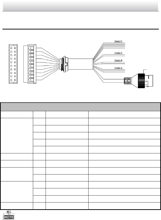
2 Terminals and Interfaces
Please refer to the following figure for terminals and interfaces of door station.
①-⑤
⑥-⑦
⑧-⑨
⑩-⑫
⑬
Figure 2-1 Terminals and Interfaces
Table 2-1 Descriptions of Terminals and Interfaces
Terminals and Interfaces
Name
No.
Color
Description
ALARM IN
1
YELLOW/BLUE
ALARM_1
2
YELLOW/ORANGE
ALARM_2
3
YELLOW/GREEN
ALARM_3
4
YELLOW/BROWN
ALARM_4
5
YELLOW/BLACK
ALARM_GND
Power Supply
6
RED
DC 12V Power Supply Input
GND
7
BLACK
Grounding
RS485
8
ORANGE
RS485+
9
YELLOW
RS485-
ALARM OUT
10
PINK
DR_NC
11
BLUE
DR_NO
12
BROWN
DR_COM
LAN
13
LAN
Network Interface
4 I/O Input terminals (ALARM_1~ALARM_4) can be set as door magnetic input or
door switch key input, and terminal ALARM_GND is for grounding connection.
1 I/O Output terminal can be enabled for controlling electric lock or disabled.