
Operation Manual


Table Of Contents
- 1 Overview
- 2 Appearance
- 3 Typical Application
- 4 Terminals and Interfaces
- 5 Installation and Wiring
- 6 Before You Start
- 7 Local Operation
- 8 Remote Operation via Batch Configuration Tool
- 9 Remote Operation via iVMS-4200
- 10 Accessing via Hik-Connect Mobile Client Software
- Appendix
Video Intercom Indoor Station·User Manual
7
4 Terminals and Interfaces
4.1 Terminals and Interfaces of DS-KH8301-WTS/
DS-KH8301-WT/DS-KH8300-T
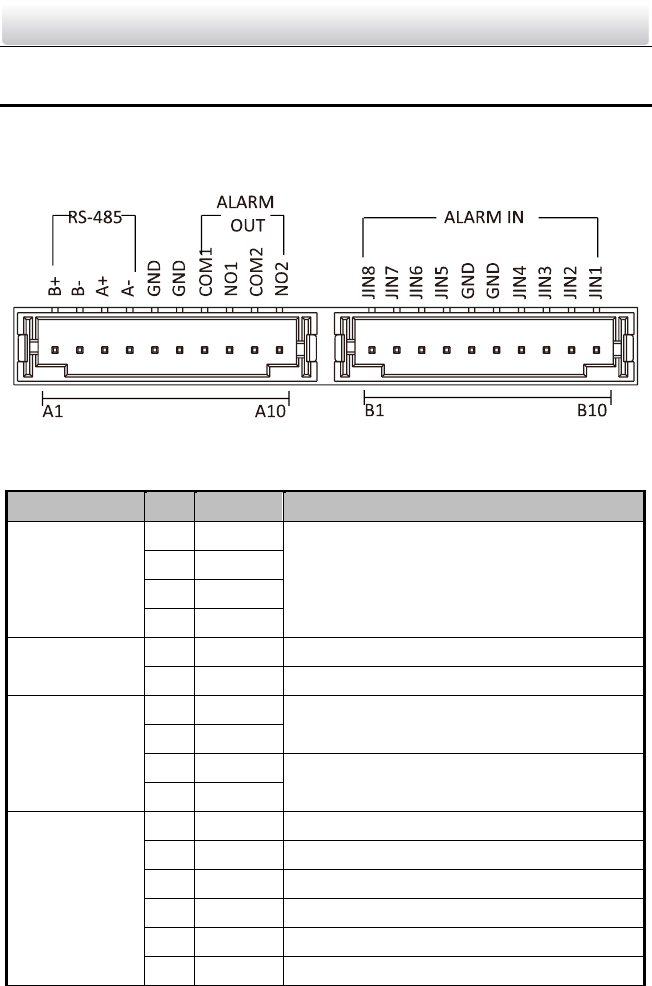
Figure 4-1 Terminals of DS-KH8301-WTS/DS-KH8301-WT/DS-KH8300-T
Table 4-1 Descriptions of Terminals and Interfaces
Name
No.
Interface
Description
485
Communication
Port
A1
RS485B+
Reserved
A2
RS485B-
A3
RS485A+
A4
RS485A-
Grounding
A5
GND
Grounding
A6
GND
Grounding
ALARM OUT
(Alarm Output)
A7
COM1
Alarm Relay Output Terminal 1 (Dry Contact)
A8
NO1
A9
COM2
Alarm Relay Output Terminal 2 (Dry Contact)
A10
NO2
ALARM IN
(Zone Input)
B1
JIN8
Zone Detector Input Terminal 8
B2
JIN7
Zone Detector Input Terminal 7
B3
JIN6
Zone Detector Input Terminal 6
B4
JIN5
Zone Detector Input Terminal 5
B5
GND
Grounding
B6
GND
Grounding