Video Intercom Indoor Station Configuration Guide
Video Intercom Indoor Station Configuration Guide Legal Information ©2021 Hangzhou Hikvision Digital Technology Co., Ltd. All rights reserved. About this Manual The Manual includes instructions for using and managing the Product. Pictures, charts, images and all other information hereinafter are for description and explanation only. The information contained in the Manual is subject to change, without notice, due to firmware updates or other reasons.
Video Intercom Indoor Station Configuration Guide CONNECTION WITH THE USE OF THE PRODUCT, EVEN IF HIKVISION HAS BEEN ADVISED OF THE POSSIBILITY OF SUCH DAMAGES OR LOSS.
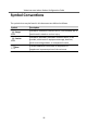
Video Intercom Indoor Station Configuration Guide Symbol Conventions The symbols that may be found in this document are defined as follows. Symbol Danger Caution Note Description Indicates a hazardous situation which, if not avoided, will or could result in death or serious injury. Indicates a potentially hazardous situation which, if not avoided, could result in equipment damage, data loss, performance degradation, or unexpected results.
Video Intercom Indoor Station Configuration Guide Regulatory Information FCC Information Please take attention that changes or modification not expressly approved by the party responsible for compliance could void the user's authority to operate the equipment. FCC compliance: This equipment has been tested and found to comply with the limits for a Class B digital device, pursuant to part 15 of the FCC Rules.
Video Intercom Indoor Station Configuration Guide EU Conformity Statement This product and - if applicable - the supplied accessories too are marked with "CE" and comply therefore with the applicable harmonized European standards listed under the EMC Directive 2014/30/EU, RE Directive 2014/53/EU,the RoHS Directive 2011/ 65/EU 2012/19/EU (WEEE directive): Products marked with this symbol cannot be disposed of as unsorted municipal waste in the European Union.
Video Intercom Indoor Station Configuration Guide 1. l'appareil ne doit pas produire de brouillage, et 2. l'utilisateur de l'appareil doit accepter tout brouillage radioélectrique subi, même si le brouillage est susceptible d'en compromettre le fonctionnement. Under Industry Canada regulations, this radio transmitter may only operate using an antenna of a type and maximum (or lesser) gain approved for the transmitter by Industry Canada.
Video Intercom Indoor Station Configuration Guide Contents 1 About this Manual ...................................................................................... 1 2 Local Operation .......................................................................................... 2 2.1 Activate Indoor Station ..................................................................................... 2 2.2 Quick Operation ................................................................................................
Video Intercom Indoor Station Configuration Guide 2.11 Output Settings ............................................................................................. 19 3 Remote Operation via the client software ............................................... 21 3.1 Activate Device Remotely ............................................................................... 21 3.2 Device Management ....................................................................................... 21 3.2.
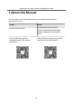
Video Intercom Indoor Station Configuration Guide 1 About this Manual Get the manual and related software from or the official website (http:// www.hikvision.com). Product Model Network Indoor Station DS-KH8520-WTE1/DS-KH6320WTE1/DS-KH6320-TE1/DS-KH6320WTE2/DS-KH8350-TE1/DS-KH8350WTE1 Scan the QR code to get the configuration guide for detailed information. Scan the QR code to get the operation guide for detailed information.
Video Intercom Indoor Station Configuration Guide 2 Local Operation 2.1 Activate Indoor Station You can configure and operate the indoor station after creating a password for the device activation. Steps 1. Power on the device. It will enter the activation page. Figure 2-1 Activation Page 2. Create a password and confirm it. 3. Optional: Bind email address. You can reset the activation/admin password via the email if you forget your password. 1) Enable Bind Email. Note By default, the function is enabled.
Video Intercom Indoor Station Configuration Guide recommend you change your password regularly, especially in the high security system, changing the password monthly or weekly can better protect your product. 2.2 Quick Operation After device activation, the wizard page will pop up. Steps 1. Choose Language and tap Next. Figure 2-2 Language Settings 2. Set network parameters and tap Next - Edit Local IP, Subnet Mask and Gateway parameters.
Video Intercom Indoor Station Configuration Guide Figure 2-3 Network Parameters 3. Configure the Hik-Connect service settings. 1) Enable Hik-Connect service. 2) Set LBS Server. 3) Set Verification Code. 4) Tap Next. 4. Configure the indoor station. 1) Choose Indoor Station Type. 2) Set SIP Password. 3) Configure advanced settings. 4) Enable Indoor Extension Settings, set Link Indoor Stations serial No. 5) Tap Next.
Video Intercom Indoor Station Configuration Guide Figure 2-4 Indoor Station Settings 5. Link related devices and tap Next. If the device and the indoor station are in the same LAN, the device will be displayed in the list. Tap the device or enter the serial No. to link. Figure 2-5 Related Device 1) Tap the door station in the list to link. Note If the door station is inactive, the system will pop up the dialog to activate the door station. 2) Tap to pop up the Network Settings page.
Video Intercom Indoor Station Configuration Guide 4) Optional: Enable Synchronize Language to synchronize the language of door station with indoor station. 5) Tap OK to save the settings. 6. Tap Finish to save the settings. 2.3 Configuration Settings Configuration settings is required before starting using the indoor station. It is necessary to set the indoor station network, room No., linked devices, device time display, and so on. 2.3.
Video Intercom Indoor Station Configuration Guide 3. Set the network parameters. - Enable DHCP, and the system can assign an IP address of the indoor station automatically. - Disable the DHCP function, and set the IP address manually. You should set the device IP address, the gateway, the DNS address. 2.3.2 Set Linked Device IP Linked network parameters refers to the network parameters of devices (like door station, doorphone, main station, center, etc.), to which the indoor station is linked.
Video Intercom Indoor Station Configuration Guide Figure 2-7 Device Information Restore the door station via indoor station. Tap to restore the parameters of the door station. Modify the IP address of the linked door station. Tap to edit the IP address of door station. 5. Select the device to link. Edit the network parameters. 2.3.3 Set Indoor Station No. Indoor station No. and the indoor extension No.
Video Intercom Indoor Station Configuration Guide Figure 2-8 Set Indoor Station Information 3. Select Indoor Station Type from Indoor Station or Indoor Extension according to your actual needs. - Indoor Station: You can set the indoor station's room information, including the room name, community No., building No., Unit No., floor, and room No., the live view duration, the SIP register password, the SIP parameters, password and E-mail address.
Video Intercom Indoor Station Configuration Guide 1) Enable Enable Standard SIP. 2) Tap VOIP Account Settings and configure the account information, including the user name, the phone number, the registered user name, the password, the domain, the port No., and the expiration date. Note Up to 32 characters are allowed in the user name. 2.3.5 Add Camera Steps 1. Tap Settings → 2. Tap → Configuration , and enter admin (activation) password. to enter the device management page. 3.
Video Intercom Indoor Station Configuration Guide Figure 2-9 Zone Settings 2. Press a zone to pop up the zone editing dialogue box. 3. Set the zone type, alarm type, status of arming status, entering delay, and exiting delay. 4. Tap OK to save the settings. Note • 7 zone types are selectable: Panic Button, Door Magnetic, Smoke Detector, Active Infrared, Passive Infrared, Gas Detector, and Doorbell. • 3 alarm types are selectable: 24h Alarm, Instant Alarm, and Delay Alarm.
Video Intercom Indoor Station Configuration Guide Before You Start Tap Settings → → Shortcut Settings to enable Alarm. Steps Note On the home page, the arming status function and zone settings function are hidden by default. You should enable the alarm function first. 1. Back to the home page, tap Settings → mode settings page. → Scene Settings to enter the arming 2. Tap Stay Mode, Away Mode, Sleeping Mode, or Custom to enter the page. Figure 2-10 Arming Mode Settings 3. Arm the selected zone.
Video Intercom Indoor Station Configuration Guide 2.4.1 Modify Unlock/Duress Code You can create and edit the duress code, unlock password and scene password of the indoor station. Steps 1. Tap Settings → → Configuration , and enter admin (activation) password. 2. Tap Password. 3. Tap Unlock, Duress Code or Scene Password to pop up the password settings dialog box. Unlock Create the indoor station's unlock password. If the device has connected to a lock, enter the password to unlock.
Video Intercom Indoor Station Configuration Guide 4. Open the E-mail to get the verification code. 5. Tap Next, and enter the verification code from the E-mail. 6. Tap Next, and create the new password. Note The new password is used for admin login, remote SDK login, SSH login, and Web login. 2.5 Synchronize Time Steps 1. Tap Settings → → Time and Date to enter the time synchronization page. Figure 2-11 Time Synchronization 2. Tap Date Format and Time Format to set the time format. 3.
Video Intercom Indoor Station Configuration Guide 2.6 Sound Settings Set the ringtone sound, the volume, and the auto answer. 2.6.1 Call Settings You can set the ringtone, ring duration, call forwarding time on call settings page. Steps 1. Tap Settings → to enter the call settings page. Figure 2-12 Call Settings 2. Set corresponding parameters. Ringtone There are 3 ringtones by default, and you can custom and import at most 4 ringtones via Batch Configuration Tool or iVMS-4200 Client Software.
Video Intercom Indoor Station Configuration Guide You can set the Do Not Disturb function. Do Not Disturb Device Select All and all devices will not disturb this device. Select Indoor Station and all indoor station will not disturb this device. Do Not Disturb Set the do not disturb schedule. Select Close and the do not disturb function will not be enabled. Select All Day and this device will not be disturbed all day. Select Schedule and you can set the do not disturb time duration.
Video Intercom Indoor Station Configuration Guide Note • Scan the left QR code on the screen to access Hik-Connect. • • Scan the right QR code on the screen to add the device to the mobile client. 2.8 Restore Indoor Station Steps 1. Tap Settings → 2. Tap → Configuration , and enter admin (activation) password. to enter the system maintenance page. 3. Tap Restore Default Settings to restore the default settings and reboot the system. 4. Tap Restore All to restore all parameters and reboot the system.
Video Intercom Indoor Station Configuration Guide You can set the displayed time and date format, current time. You can also tap Sync Time and enable NTP to synchronize the device time. Note • Make sure your device is connected with the network or the NTP function will not available. • For details, see Synchronize Time. System Language Tap System Language to change the system language. Note The indoor station supports 11 languages. Brightness Adjustment Tap + or - to adjust the screen brightness.
Video Intercom Indoor Station Configuration Guide Unbound EZVIZ Account Unlink the Hik-Connect account from the platform. Wizard Tap Wizard and set the language, network, indoor station type, device No., and select a device according to the wizard. Tap Settings → to enter the preference page. Shortcut Settings Enable call elevator, alarm, call management center, or leave message and the icon will be displayed on the home page.
Video Intercom Indoor Station Configuration Guide You can set and control the connected output devices via the output settings page. You can change the relay' name, and open duration. You can also set to display the relay button on the main page or not. Steps 1. Tap Settings → → Output Settings . Note • Supports up to 2 relays. • If no relays displayed on the page, the device may not support the function. 2. Select a relay and set the parameters. Name You can change the relay's name.
Video Intercom Indoor Station Configuration Guide 3 Remote Operation via the client software The Video Intercom module provides remote control and configuration on video intercom products via the iVMS-4200 client software. 3.1 Activate Device Remotely You can only configure and operate the indoor station after creating a password for the device activation. Before You Start Default parameters of indoor station are as follows: • Default IP Address: 192.0.0.64. • Default Port No.: 8000.
Video Intercom Indoor Station Configuration Guide Device management includes device activation, adding device, editing device, and deleting device, and so on. After running the iVMS-4200, video intercom devices should be added to the client software for remote configuration and management. 3.2.1 Add Video Intercom Devices Steps Note • You can add at most 512 indoor stations and main stations in total to the client, and add at most 16 door stations to the client.
Video Intercom Indoor Station Configuration Guide Figure 3-1 Add the Device 4. Optional: Click Online Device, the active online devices in the same local subnet with the client software will be displayed on the Online Device area. Note To add online devices to the software, you are required to change the device IP address to the same subnet with your computer first. 1) You can click Refresh Every 60s to refresh the information of the online devices. 2) Select the devices to be added from the list.
Video Intercom Indoor Station Configuration Guide Edit a name for the device as you want. Address Input the device's IP address. The IP address of the device is obtained automatically in this adding mode. Port Input the device port No. The default value is 8000. User Name Input the device user name. By default, the user name is admin. Password Input the device password. By default, the password is 12345. 6. Optional: You can check the checkbox Export to Group to create a group by the device name.
Video Intercom Indoor Station Configuration Guide 3.3 System Configuration You can configure the video intercom parameters accordingly. Steps 1. Click Maintenance and Management → System Configuration → ACS & Video Intercom to enter the system configuration page. 2. Enter the required information. Ringtone Click ... and select the audio file from the local path for the ringtone of indoor station. Optionally, you can click for a testing of the audio file.
Video Intercom Indoor Station Configuration Guide Device Information Click Device Information to enter device basic information page. You can view basic information (the device type, and serial No.), and version information of the device. Figure 3-2 Device Information General Click General to enter device general parameters settings page. You can view and edit the device name and device ID, and select overwrite record file. Figure 3-3 General Time Click Time to enter the device time settings page.
Video Intercom Indoor Station Configuration Guide Figure 3-4 Time Settings Page Select Time Zone, Enable NTP, Enable DST, or SDK Synchronization. Click Save to save the time settings. • Time Zone: Select a time zone from the drop-down list menu. • NTP: Click Enable NTP, and enter the server address, NTP port, and synchronization interval. Note The default port No. is 123. • DST: Click Enable DST, and set the start time, end time, and bias.
Video Intercom Indoor Station Configuration Guide Figure 3-5 System Maintenance • Reboot: Click Reboot and the system reboot dialog box pops up. Click Yes to reboot the system. • Restore Default Settings: Click Restore Default Settings to restore the default parameters. All default settings, excluding network parameters, will be restored. • Restore All: Click Restore All to restore all parameters of device and reset the device to inactive status.
Video Intercom Indoor Station Configuration Guide • Remote Upgrade: Click ... to select the upgrade file and click Upgrade to remote upgrade the device. The process of remote upgrade will be displayed in the process bar. • Language: Select a language, and click Save to change the device system language.
Video Intercom Indoor Station Configuration Guide Note • The new password and confirm password should be identical. • After editing the password of device, click refresh button from the device list, the added device will not be there. You should add the device again with new password to operate the remote configuration. RS-485 Click RS485 to enter the RS-485 settings page. You can view and edit the RS-485 parameters of the device.
Video Intercom Indoor Station Configuration Guide Figure 3-8 Security 3.4.2 Video Intercom Click Video Intercom on the remote configuration page to enter the video intercom parameters settings: Time Parameters, Password, Zone Configuration, IP Camera Information, Volume Input and Output Configuration, Ring, Arming Information, Calling Linkage, Relay, and SIP No. Time Parameters Steps 1. Click Time Parameters to enter time parameters settings page. Figure 3-9 Time Parameters 2.
Video Intercom Indoor Station Configuration Guide 3. Click Save. Note • Calling duration is the maximum duration of indoor station when it is called without being received. The range of maximum ring duration varies from 30s to 60s. • Live view duration is the maximum time of playing live view of the indoor station. The range of maximum live view time varies from 10s to 60s.
Video Intercom Indoor Station Configuration Guide Figure 3-11 Zone Alarm 2. Select Area No. 3. Select Zone Type from the drop-down list. 4. Select Alarm Type from the drop-down list. 5. Set the NO/NC status. 6. Set Entering Delay and Exiting Delay. 7. Select relays. 8. Click Save to enable zone settings. Note • 7 zone types are supported: Emergency Switch, Door Magnetic Switch, Smoke Detector, Active IR Detector, Passive IR Detector, Combustible Gas Detector, and DoorBell Switch.
Video Intercom Indoor Station Configuration Guide • When the zone type is set to be 24H Alarm, the indoor station will receive alarm message when the detector is triggered no matter it is under arming mode or disarming mode. • When the zone type is set to be Delay Alarm, only under arming mode, the indoor station will receive alarm message when the detector is triggered. Under disarming mode, it will not receive alarm message when the detector is triggered.
Video Intercom Indoor Station Configuration Guide Export and Import Added Device Information Steps 1. Click Export to export the added device information file. 2. Edit parameters of added devices in batch in the exported file. 3. Click Import to pop up importing box, and open the edited added device information file. Figure 3-13 Import Added Device Information Volume Input and Output Steps 1. Click Volume Input/Output to enter the configuring the volume input or output page.
Video Intercom Indoor Station Configuration Guide Figure 3-14 Volume Input or Output 2. Slide the slider to adjust the input volume, output volume and speak volume. 3. Click Save to enable the settings. Ring Import Steps 1. Click Ring Import to enter the ring configuration page. Figure 3-15 Ring Import 2. Click + to add the ring, and click x to delete the imported ring. Note • The ring to be imported should be in the wav format, and the size of the ring cannot be larger than 300k.
Video Intercom Indoor Station Configuration Guide Click Arming Information to enter the configuring arming informaton page and view the arming information. Figure 3-16 Arming Information Click Refresh to refresh the arming information. Calling Linkage Steps 1. Click Calling Linkage to enter the set the calling linkage page. Figure 3-17 Calling Linkage 2. Enable and select relays. When the calling is incoming, the alarm you linked will be relayed. Relay Click Relay to enter the set relay parameters page.
Video Intercom Indoor Station Configuration Guide Steps 1. Click Extension Settings to enter the extension settings page. Figure 3-18 Extension Settings 2. Click Add.
Video Intercom Indoor Station Configuration Guide 3. Select Device Type as Indoor Extension. 4. Enter the required information. Serial No. Enter the device's serial No.. The serial No. is on the rear panel of the device (A fixed-length number with 9 digits). IP Address Enter the device's IP address. Gateway Enter the device's gateway. Subnet Mask Enter the device's subnet mask. Password Enter the device password, ranging from 8 to 16 characters in length. No. Enter the device No., ranging from 1 to 5. 5.
Video Intercom Indoor Station Configuration Guide Figure 3-20 Local Network Configuration 2. Enter the local IP address, IP address subnet mask, gateway, port No. and HTTP port No.. 3. Click Save to enable the settings. Note • The default port No. is 8000. • After editing the local network parameters of device, you should add the devices to the device list again. SIP Server Configuration Steps 1. Click SIP Server Configuration to enter the configuring the SIP parameters page.
Video Intercom Indoor Station Configuration Guide Figure 3-21 SIP Server Configuration 2. Click Enable. 3. Set the parameters according to your needs. Note • Up to 32 characters are allowed in the Register User Name field. • Registration password should be 1 to 16 characters in length. • Up to 32 characters are allowed in the Number field. • The device location should contain 1 to 32 characters. • The registration period should be between 15 minutes to 99 minutes. 4.
Video Intercom Indoor Station Configuration Guide Figure 3-22 DNS Settings Configure Mobile Client Connection Configure Hik-Connect server parameters before viewing videos via mobile client. Before You Start Make sure the indoor station connects to the network. Steps 1. Click Hik-Connect to enter the configuring the Hik-Connect settings page. 2. Enable Enable Hik-Connect. Note • To enable Hik-Connect service, you need to create a verification code or change the verification code.
Video Intercom Indoor Station Configuration Guide Figure 3-23 Group Network Settings Device Number Settings Select the device type from the drop-down list, and set the corresponding information. Note • Device type can be set as indoor station or indoor extension. • Device number ranges from 1 to 5. Click Save to enable the settings. Linked Device Network Settings Enter Registration Password and set the corresponding information. Note • D series refers to door station, and V series refers to villa station.
Video Intercom Indoor Station Configuration Guide Figure 3-24 Personal Management Application The page is divided into two parts: Organization Management and Person Management. Organization Management You can add, edit, or delete the organization as desired. Person Management After adding the organization, you can add the person to the organization and issue card to persons for further management. 3.5.
Video Intercom Indoor Station Configuration Guide Note Up to 10 levels of organizations can be created. Modify and Delete Organization You can select the added organization and click to modify its name. You can select an organization, and click X button to delete it. Note • The lower-level organizations will be deleted as well if you delete an organization. • Make sure there is no person added under the organization, or the organization cannot be deleted. 3.5.
Video Intercom Indoor Station Configuration Guide 2) Optional: Click Add Face to upload the photo. Note The picture should be in *.jpg format. Click Upload Select the person picture from the local PC to upload it to the client. Click Take Phone Take the person's photo with the PC camera. Click Remote Collection Take the person's photo with the collection device. 3. Issue the card for the person. 1) Click Credential → Card . 2) Click + to pop up the Add Card dialog. 3) Select Normal Card as Card Type.
Video Intercom Indoor Station Configuration Guide 4) Click OK to start exporting. 2. Importing Person: You can import the Excel file with persons information in batch from the local PC. 1) Click Import Person. 2) You can click Download Template for Importing Person to download the template first. 3) Input the person information to the downloaded template. 4) Click ... to select the Excel file with person information. 5) Click OK to start importing.
Video Intercom Indoor Station Configuration Guide Select the person and click Edit to open the editing person dialog. To delete the person, select a person and click Delete to delete it. Note If a card is issued to the current person, the linkage will be invalid after the person is deleted. Change Person to Other Organization You can move the person to another organization if needed. Steps 1. Select the person in the list and click Change Organization. 2. Select the organization to move the person to. 3.
Video Intercom Indoor Station Configuration Guide A. Communication Matrix and Device Command Communication Matrix Scan the following QR code to get the device communication matrix. Note that the matrix contains all communication ports of Hikvision access control and video intercom devices. Figure A-1 QR Code of Communication Matrix Device Command Scan the following QR code to get the device common serial port commands.
UD22939B