Video Intercom Indoor Station Quick Start Guide UD02902B
Video Intercom Indoor Station·Quick Start Guide Quick Start Guide © 2016 Hangzhou Hikvision Digital Technology Co., Ltd. This quick start guide is intended for users of the models below: Series Model DS-KH6310-W DS-KH6310 Indoor Station (6-Series) DS-KH6310-WL DS-KH6210-L DS-KH8301-WTS Indoor Station (8-Series) DS-KH8301-WT DS-KH8300-T It includes instructions on how to use the Product. The software embodied in the Product is governed by the user license agreement covering that Product.
Video Intercom Indoor Station·Quick Start Guide TO THE MAXIMUM EXTENT PERMITTED BY APPLICABLE LAW, IN NO EVENT WILL HIKVISION, ITS DIRECTORS, OFFICERS, EMPLOYEES, OR AGENTS BE LIABLE TO YOU FOR ANY SPECIAL, CONSEQUENTIAL, INCIDENTAL, OR INDIRECT DAMAGES, INCLUDING, AMONG OTHERS, DAMAGES FOR LOSS OF BUSINESS PROFITS, BUSINESS INTERRUPTION, SECURITY BREACHES, OR LOSS OF DATA OR DOCUMENTATION, IN CONNECTION WITH THE USE OF OR RELIANCE ON THIS MANUAL, EVEN IF HIKVISION HAS BEEN ADVISED OF THE POSSIBILITY OF SUC
Video Intercom Indoor Station·Quick Start Guide Regulatory Information FCC Information Please take attention that changes or modification not expressly approved by the party responsible for compliance could void the user’s authority to operate the equipment. FCC compliance: This equipment has been tested and found to comply with the limits for a Class A digital device, pursuant to part 15 of the FCC Rules.
Video Intercom Indoor Station·Quick Start Guide The precaution measure is divided into Warnings and Cautions: Warnings: Neglecting any of the warnings may cause serious injury or death. Cautions: Neglecting any of the cautions may cause injury or equipment damage. Warnings Follow these safeguards to prevent serious injury or death. Cautions Follow these precautions to prevent potential injury or material damage.
Video Intercom Indoor Station·Quick Start Guide Please use the provided glove when open up the device cover, avoid direct contact with the device cover, because the acidic sweat of the fingers may erode the surface coating of the device cover. Please use a soft and dry cloth when clean inside and outside surfaces of the device cover, do not use alkaline detergents. Please keep all wrappers after unpack them for future use.
Video Intercom Indoor Station·Quick Start Guide Table of Contents 1 Appearance ...............................................................................................................1 1.1 Appearance of DS-KH8301-WTS/DS-KH8301-WT/ DS-KH8300-T ............................. 1 1.2 Appearance of DS-KH6310-W/DS-KH6310 .............................................................. 2 1.3 Appearance of DS-KH6310-WL/DS-KH6210-L ..........................................................
Video Intercom Indoor Station·Quick Start Guide Appendix ................................................................................................................... 33 Installation Notice ....................................................................................................... 33 Wiring Cables ..............................................................................................................
Video Intercom Indoor Station·Quick Start Guide 1 Appearance 1.1 Appearance of DS-KH8301-WTS/DS-KH8301-WT/ DS-KH8300-T Table 1-1 Components Description Figure 1-1 Front Panel No. Description 1 Built-in Camera (Only DS-KH8301-WT supports) 2 Power Supply Indicator 3 Information Indicator 4 Alarm Indicator 5 SOS Touch Key 6 Unlock Touch Key 7 Live View Touch Key 8 Management Center Touch Key 9 LCD Display Screen 10 Microphone Table 1-2 Components Description Figure 1-2 Rear Panel No.
Video Intercom Indoor Station·Quick Start Guide 1.2 Appearance of DS-KH6310-W/DS-KH6310 Table 1-3 Components Description Figure 1-3 Front Panel No. Description 1 Power Supply Indicator 2 Information Indicator 3 Alarm Indicator 4 SOS Key 5 Unlock Key 6 Live View Key 7 Management Center Key 8 LCD Display Screen 9 Microphone Table 1-4 Components Description No.
Video Intercom Indoor Station·Quick Start Guide 1.3 Appearance of DS-KH6310-WL/DS-KH6210-L Table 1-5 Components Description Figure 1-5 Front Panel No. Description 1 Power Supply Indicator 2 Information Indicator 3 Alarm Indicator 4 SOS Key 5 Unlock Key 6 Live View Key 7 Management Center Key 8 LCD Display Screen 9 Microphone Table 1-6 Components Description No.
Video Intercom Indoor Station·Quick Start Guide Keys Hold Down Press SOS Key Return Key Direction Keys▲and◄/Unlock Key Live View Key Alarm Direction Keys▼and► Management Center Key Confirm Key 4
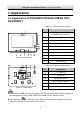
Video Intercom Indoor Station·Quick Start Guide 2 Terminals and Interfaces 2.1 Terminals and Interfaces of DS-KH8301-WTS/ DS-KH8301-WT/DS-KH8300-T Figure 2-1 Terminals of DS-KH8301-WTS/DS-KH8301-WT/DS-KH8300-T Table 2-1 Descriptions of Terminals and Interfaces Name 485 Communication Port Grounding ALARM OUT (Alarm Output) ALARM IN (Zone Input) No.
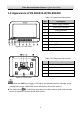
Video Intercom Indoor Station·Quick Start Guide Name No. Interface Description B7 JIN4 Zone Detector Input Terminal 4 B8 JIN3 Zone Detector Input Terminal 3 B9 JIN2 Zone Detector Input Terminal 2 B10 JIN1 Zone Detector Input Terminal 1 2.2 Terminals and Interfaces of DS-KH6310-W/ DS-KH6310 Figure 2-2 terminals of DS-KH6310-W/DS-KH6310 Table 2-2 Descriptions of Terminals and Interfaces Name Terminals No.
Video Intercom Indoor Station·Quick Start Guide 2.3 Terminals and Interfaces of DS-KH6310-WL/ DS-KH6210-L Figure 2-3 Terminals of DS-KH6310-WL/DS-KH6210-L Table 2-3 Terminals Description Name Terminals No.
Video Intercom Indoor Station·Quick Start Guide 3 Installation and Wiring Before you start: Make sure the device in the package is in good condition and all the assembly parts are included. The power supply the indoor station supports is 12 VDC. Please make sure your power supply matches your indoor station. Make sure all the related equipment is power-off during the installation. Check the product specification for the installation environment. 3.
Video Intercom Indoor Station·Quick Start Guide Steps: 1. Chisel a hole in the wall. The size of the hole should be 76 mm (width) × 76 mm (length) × 50 mm (depth). 2. Insert the junction box to the hole chiseled on the wall. 3. Fix the wall mounting plate to the junction box with 2 screws. Wall Mounting Plate Screws Junction Box Figure 3-2 Installing the Plate 4.
Video Intercom Indoor Station·Quick Start Guide 3.2 Indoor Station Wiring 3.2.
Video Intercom Indoor Station·Quick Start Guide 3.2.
Video Intercom Indoor Station·Quick Start Guide 3.2.
Video Intercom Indoor Station·Quick Start Guide Descriptions of Indoor Station interfaces are shown in the following table. Interface Description ALARM IN Connect alarm device, with one end of the device connecting to JINx and the other end connecting to GND (x indicates number between 1~8). ALARM OUT Connect alarm output devices. GND 12V Connect to DC power supply 12V. LAN Network port of indoor station. Connect the indoor station to the same LAN with the door station.
Video Intercom Indoor Station·Quick Start Guide 4 Before You Start For the first time use of the device, you are required to activate the device and set the device password. You can activate the device on the UI, via internet with Batch Configuration Tool, or with iVMS-4200 client software. To activate the device on the UI, refer to chapter 5 and enter the configuration password. To activate the device with Batch Configuration Tool or iVMS-4200, refer to 6.1 and the user manual in the disk.
Video Intercom Indoor Station·Quick Start Guide 5 Local Operation Here the local operation of indoor stations with touch screen is taken as example. The DS-KH6210-L should be operated with physical keys. The SOS key works as a return key; the Unlock key works as direction keys ▲and◄ to turn up and left; the Live View key works as direction keys ▼and► to turn down and right; and the Management Center key works as a confirm key. 5.1 Activating Device Locally Steps: 1.
Video Intercom Indoor Station·Quick Start Guide You must create a password to activate the device for your first time usage and when it is not activated. Only when the device is activated, can you operate it locally and remotely. Here the activation interface of DS-KH8301-WT indoor station is taken as example. 5.2 User Interface Description 5.2.
Video Intercom Indoor Station·Quick Start Guide Slide left and right to realize the switch between two interface pages (except for DS-KH6210-L). Here the user interface of DS-KH8301-WT is taken as as example. Only DS-KH8301-WTS/DS-KH8301-WT/DS-KH8300-T indoor stations support TF card. DS-KH6210-L only has one interface page. Figure 5-4 User Interface of DS-KH6210-L 5.2.
Video Intercom Indoor Station·Quick Start Guide Only DS-KH8301-WTS/DS-KH8301-WT/DS-KH8300-T indoor extensions support TF card. Here the user interface of DS-KH8301-WT indoor extension is taken as example. 5.2.3 Status of Indoor Station Table 5-1 Description of Status Icons Icon Definition Description Normal Status. The communication between indoor station, door station and master station is normal. And the communication between indoor station and indoor extension is normal.
Video Intercom Indoor Station·Quick Start Guide Icon Definition Description TF card is inserted in the indoor station. Exception occurs with the TF card. Only DS-KH8301-WTS/DS-KH8301-WT/ DS-KH8300-T Models support the TF card function. No TF card is inserted in the indoor station. 5.2.4 Status of Indoor Extension Table 5-2 Description of Status Icons Icon Definition Description Normal Status. The communication between indoor station and indoor extension is normal. The indoor extension is offline.
Video Intercom Indoor Station·Quick Start Guide Icon Definition Description No TF card is inserted in the station station. 5.3 Configuration Settings Purpose: On the configuration settings interface, you can set and view the local information, configure the network, manage devices, synchronize the device time, and restore the default settings. You can get to the configuration interface: Settings > Configuration. 5.3.
Video Intercom Indoor Station·Quick Start Guide Figure 5-6 Local Information Settings (Indoor Station) Figure 5-7 Local Information Settings (Indoor Extension) 3. Press the drop-down list to select a video standard: PAL, or NTSC. 4. Set the maximum live view duration of the device. The Extension No. is numeric from 1 to 5, i.e., up to 5 indoor extensions can connect to one indoor station.
Video Intercom Indoor Station·Quick Start Guide Only DS-KH8301-WT, DS-KH8301-WTS and DS-KH8501-WT require setting the video standard, and the system will reboot after selecting video standard. The maximum live view duration varies from 10 seconds to 60 seconds. 5.3.3 Setting Network Purpose: Network connection is mandatory for the use of the indoor station. Steps: 1. Get to the configuration interface: Settings > Configuration, and enter the admin password (configuration password). 2.
Video Intercom Indoor Station·Quick Start Guide 5. Press the tab to save the settings. Enable DHCP function to obtain an IP address automatically. Enable Same LAN function if indoor stations and indoor extensions are in the same local area network with other video intercom devices in a community, or the indoor extensions will not work normally. 5.3.4 Adding Device Adding Device (Indoor Station) Purpose: The indoor station never works alone.
Video Intercom Indoor Station·Quick Start Guide Figure 5-10 Main Door Station Adding Interface (Indoor Station) 4. Select the main door station type: D Series, or V Series. 5. Enter the IP address of the main door station, and press the settings. tab to save the Adding IP Camera Steps: 1. Get to the configuration interface: Settings > Configuration, and enter the admin password (configuration password). 2. Press the Device tab to enter the device management interface. 3. Press the Add Device tab.
Video Intercom Indoor Station·Quick Start Guide Figure 5-11 Device Selecting Interface (Indoor Station) 4. Press the IP Camera tab to pop up the IP camera adding dialogue box. Figure 5-12 IP Camera Adding Interface 5. Enter the device name, IP address, Port No., user name, and password. 6. Press the tab to save the settings. The default port No. is 554, and the default user name is admin. When the IP camera is added successfully, you can get the live view of IP camera on the live view interface.
Video Intercom Indoor Station·Quick Start Guide Adding Device (Indoor Extension) Indoor extension can only connect to the indoor station. Steps: 1. Get to the configuration interface: Settings > Configuration, and enter the admin password (configuration password). 2. Press the Device tab to enter the device management interface. 3. Press the Indoor Station tab to pop up the device information dialogue box. Figure 5-13 Indoor Station Adding Interface (Indoor Extension) 4.
Video Intercom Indoor Station·Quick Start Guide Indoor extension does not support this function. On the call resident interface of DS-KH6210-L, there is no Contact List, Call Elevator, or Call Center tab.
Video Intercom Indoor Station·Quick Start Guide 6 Remote Operation (Batch Configuration Tool) 6.1 Activating Device Remotely Purpose: You are required to activate the device first by setting a strong password for it before you can use the device. Activation via Batch Configuration Tool, and Activation via iVMS-4200 are supported. Here take activation via Batch Configuration Tool as example to introduce the device activation. Please refer to the user manual for the activation via iVMS-4200. Steps: 1.
Video Intercom Indoor Station·Quick Start Guide STRONG PASSWORD RECOMMENDED– We highly recommend you create a strong password of your own choosing (Using a minimum of 8 characters, including at least three of the following categories: upper case letters, lower case letters, numbers, and special characters.) in order to increase the security of your product.
Video Intercom Indoor Station·Quick Start Guide Figure 6-4 Editing Network Parameters The default port No. is 8000. After editing the network parameters of device, you should add the devices to the device list again. 6.3 Adding Device For batch configuration tool and iVMS-4200 software, you should add device to the software so as to configure the device remotely.
Video Intercom Indoor Station·Quick Start Guide 2. Click the button to pop up the login dialog box. Figure 6-6 Login Dialog Box 3. Enter the user name and password. 4. Click the OK button to save the settings. Only devices successfully logged in will be added to the device list for configuration. If you add devices in batch, please make sure selected devices have the same user name and password. 6.3.2 Adding by IP Address Purpose: You can add the device by entering IP address. Steps: 1.
Video Intercom Indoor Station·Quick Start Guide Figure 6-8 Adding by IP Address 4. Click the OK button to add the device to the device list. You cannot add the device(s) to the device list if the user name and password are not identical. When you add devices by IP Address, IP Segment or Port No., the devices should be online devices.
Video Intercom Indoor Station·Quick Start Guide Appendix Installation Notice While installing the indoor station, please make sure that the distance between any two devices is far as possible to avoid the howling and echo. The distance between two devices is recommended to be more than 10 meters. Here the devices refer to indoor station, outdoor station and master station. Wiring Cables Cable Specification Power Cord of Door Station RVV 2*1.
Video Intercom Indoor Station·Quick Start Guide 34