
Installation Guide

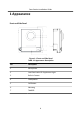
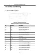
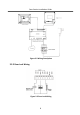
Table Of Contents
2 Terminal and Wiring
2.1 Terminal Descripon
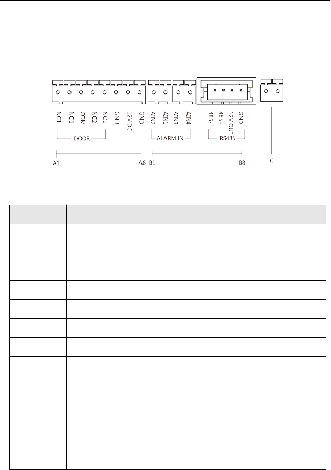
Figure 2-1 Terminals and Interfaces
Table 2-1 Descripons of Terminals and Interfaces
No. Interface Descripon
A1 NC1 Door Lock Relay Output (NC)
A2 NO1 Door Lock Relay Output (NO)
A3 COM Common Interface
A4 NC2 Door Lock Relay Output (NC)
A5 NO2 Door Lock Relay Output (NO)
A6 GND Grounding
A7 12 VDC Power Supply Output
A8 GND Grounding
B1 AIN1 For the access of Door Magnec 2
B2 AIN2 For the access of Door Magnec 1
B3 AIN3 For the access of Exit Buon 1
B4 AIN4 For the access of Exit Buon 2
B5 485- Module-connecng Interface
Door Staon Installaon Guide
3