Installation Guide
Manuals
Brands
Hikvision Manuals
Video Intercom Products
Two wire main unit
1
2
3
4
5
6
7
8
9
10
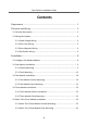
Table Of Contents
Symbol Conventions
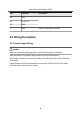
1 Appearance
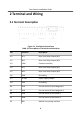
2 Terminal and Wiring
2.1 Terminal Description
2.2 Wiring Description
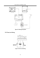
2.2.1 Power Supply Wiring
2.2.2 Door Lock Wiring
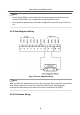
2.2.3 Door Magnetic Wiring
2.2.4 Exit Button Wiring
3 Installation
3.1 Configure Sub Module Address
3.2 One-Module Installation
3.2.1 Surface Mounting
3.2.2 Flush Mounting
3.3 Two-Module Installation
3.3.1 Two-Module Surface Mounting
3.3.2 Two-Module Flush Mounting
3.4 Three-Module Installation
3.4.1 Three-Module Surface Installation
3.4.2 Three-Module Flush Mounting
3.5 More-Than-Three Module Installation
3.5.1 More-Than-Three Module Surface Mounting
3.5.2 More-Than-Three Module Flush Mounting
A. Extension Modules
B. Cables
Boom
Panel
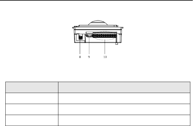
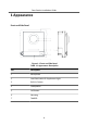
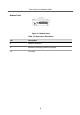
Figure 1-2
Boom
P
anel
T
able 1-2 Appearance
Descripon
No.
Descripon
8
Network Int
erface
9
Module-connecng
Interf
ace (output)
10
T
erminals
Door
Staon
Inst
allaon
Guide
2
1
...
...
4
5
6
7
8
...
...
55