Installation Guide
Manuals
Brands
Hikvision Manuals
Video Intercom Products
Two wire main unit
31
32
33
34
35
36
37
38
39
40
Table Of Contents
Symbol Conventions
1 Appearance
2 Terminal and Wiring
2.1 Terminal Description
2.2 Wiring Description
2.2.1 Power Supply Wiring
2.2.2 Door Lock Wiring
2.2.3 Door Magnetic Wiring
2.2.4 Exit Button Wiring
3 Installation
3.1 Configure Sub Module Address
3.2 One-Module Installation
3.2.1 Surface Mounting
3.2.2 Flush Mounting
3.3 Two-Module Installation
3.3.1 Two-Module Surface Mounting
3.3.2 Two-Module Flush Mounting
3.4 Three-Module Installation
3.4.1 Three-Module Surface Installation
3.4.2 Three-Module Flush Mounting
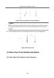
3.5 More-Than-Three Module Installation
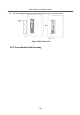
3.5.1 More-Than-Three Module Surface Mounting
3.5.2 More-Than-Three Module Flush Mounting
A. Extension Modules
B. Cables
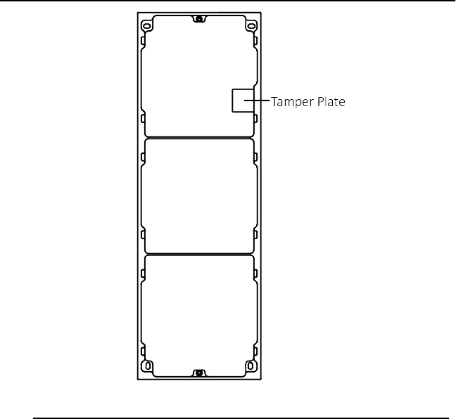
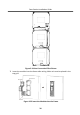
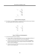
Figure 3-32
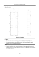
Mounng
Fr
ame
5.
Thread the
module-connecng
lines acr
oss the thread holes of the fr
ame. Pass
the main unit
connecng
lines across the thr
ead hole to the top grid.
Door
Staon
Inst
allaon
Guide
28
1
...
...
30
31
32
33
34
...
...
55