Installation Guide
Manuals
Brands
Hikvision Manuals
Video Intercom Products
Two wire main unit
31
32
33
34
35
36
37
38
39
40
Table Of Contents
Symbol Conventions
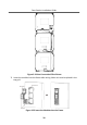
1 Appearance
2 Terminal and Wiring
2.1 Terminal Description
2.2 Wiring Description
2.2.1 Power Supply Wiring
2.2.2 Door Lock Wiring
2.2.3 Door Magnetic Wiring
2.2.4 Exit Button Wiring
3 Installation
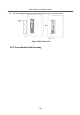
3.1 Configure Sub Module Address
3.2 One-Module Installation
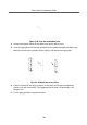
3.2.1 Surface Mounting
3.2.2 Flush Mounting
3.3 Two-Module Installation
3.3.1 Two-Module Surface Mounting
3.3.2 Two-Module Flush Mounting
3.4 Three-Module Installation
3.4.1 Three-Module Surface Installation
3.4.2 Three-Module Flush Mounting
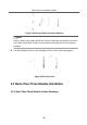
3.5 More-Than-Three Module Installation
3.5.1 More-Than-Three Module Surface Mounting
3.5.2 More-Than-Three Module Flush Mounting
A. Extension Modules
B. Cables
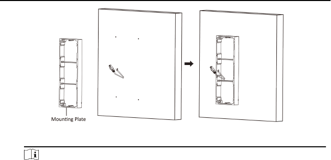
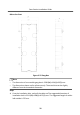
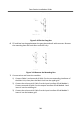
Figure 3-31 Fix the
Mounng
Fr
ame
Note
The
mounng
frame should be placed e
xactly as below f
or this step. The tamper
plate should be a
t the low right of the
rs
t
grid.
Door
Staon
Inst
allaon
Guide
27
1
...
...
29
30
31
32
33
...
...
55