Installation Guide
Manuals
Brands
Hikvision Manuals
Video Intercom Products
Two wire main unit
11
12
13
14
15
16
17
18
19
20
Table Of Contents
Symbol Conventions
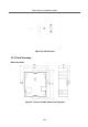
1 Appearance
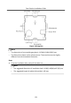
2 Terminal and Wiring
2.1 Terminal Description
2.2 Wiring Description
2.2.1 Power Supply Wiring
2.2.2 Door Lock Wiring
2.2.3 Door Magnetic Wiring
2.2.4 Exit Button Wiring
3 Installation
3.1 Configure Sub Module Address
3.2 One-Module Installation
3.2.1 Surface Mounting
3.2.2 Flush Mounting
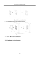
3.3 Two-Module Installation
3.3.1 Two-Module Surface Mounting
3.3.2 Two-Module Flush Mounting
3.4 Three-Module Installation
3.4.1 Three-Module Surface Installation
3.4.2 Three-Module Flush Mounting
3.5 More-Than-Three Module Installation
3.5.1 More-Than-Three Module Surface Mounting
3.5.2 More-Than-Three Module Flush Mounting
A. Extension Modules
B. Cables
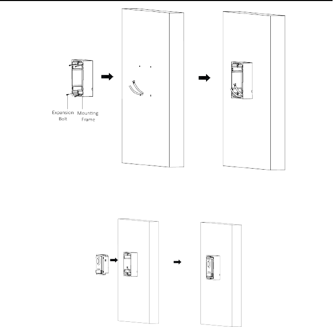
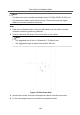
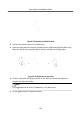
Figure 3-4 Fix the
Mounng
Fr
ame
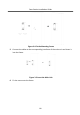
5.
Connect the cables to the corr
esponding interfaces of the main unit and insert it
into the fr
ame.
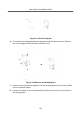
Figure 3-5 Insert the Main Unit
6.
Fix the cover on
to the fr
ame.
Door
Staon
Inst
allaon
Guide
11
1
...
...
13
14
15
16
17
...
...
55