
Installation Guide
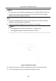
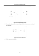
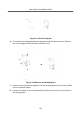
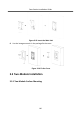
Table Of Contents
3 Installaon
Note
•
Make sure the device in the package is in good condion and all the assembly
parts are included.
•
Make sure the place for surface mounng is at.
•
Make sure all the related equipment is power-o during the installaon.
•
Tools that you need to prepare for installaon:
Drill (ø6), cross screwdriver (PH1*150 mm), and gradienter.
3.1 Congure Sub Module Address
You need to set the sub module address via DIP before installaon.
Steps
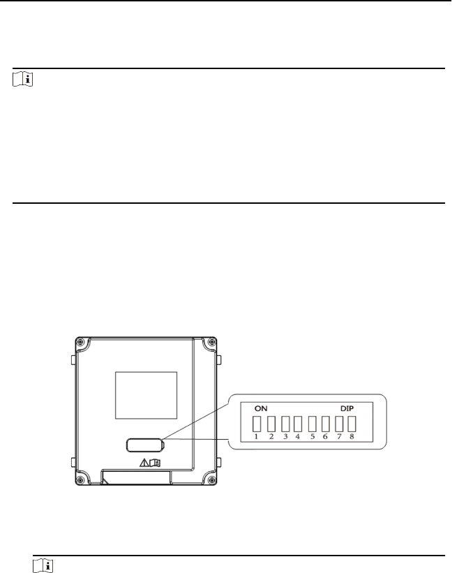
1.
Remove the rubber cover on the sub module rear panel to expose the DIP
switch.
Figure 3-1 DIP Switch
2.
Set the sub module address according to the DIP rules, and install the rubber
cover back.
Note
•
Digit 1, 2, 3, 4 are used to coding the sub module address; Digit 5, 6, 7 are
reserved; Digit 8 is a resistance (120Ω) is you set it as on.
•
Valid sub module address range is 1 to 8. The No. should be unique for sub
modules that connected to the same main unit.
Door Staon Installaon Guide
8