Door Station Installation Guide
Door Station Installation Guide Symbol Conventions The symbols that may be found in this document are defined as follows. Symbol Danger Caution Note Description Indicates a hazardous situation which, if not avoided, will or could result in death or serious injury. Indicates a potentially hazardous situation which, if not avoided, could result in equipment damage, data loss, performance degradation, or unexpected results.
Door Station Installation Guide Contents 1 Appearance ................................................................................................ 1 2 Terminal and Wiring ................................................................................... 3 2.1 Terminal Description ......................................................................................... 3 2.2 Wiring Description ............................................................................................ 4 2.2.
Door Station Installation Guide A. Extension Modules .................................................................................. 49 B. Cables ......................................................................................................
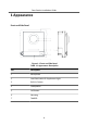
Door Station Installation Guide 1 Appearance Front and Side Panel Figure 1-1 Front and Side Panel Table 1-1 Appearance Description No.
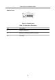
Door Station Installation Guide Bottom Panel Figure 1-2 Bottom Panel Table 1-2 Appearance Description No.
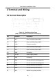
Door Station Installation Guide 2 Terminal and Wiring 2.1 Terminal Description Figure 2-1 Terminals and Interfaces Table 2-1 Descriptions of Terminals and Interfaces No.
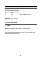
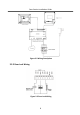
Door Station Installation Guide No. Interface B6 485+ B7 12 V OUT B8 GND C LAN Description Power and Network Interface 2.2 Wiring Description 2.2.1 Power Supply Wiring Caution Make sure all the related equipment is power-off during the installation. Wire the devices with power supply cables as picture shown below. Door station should be connected to CH6 of the video/audio distributor with twowire cables.
Door Station Installation Guide Figure 2-2 Wiring Description 2.2.
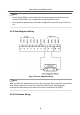
Door Station Installation Guide Note • Terminal NC1/COM is set as default for accessing magnetic lock/electric bolt; terminal NO2/COM is set as default for accessing electric strike. • Lock should be powered by itself. Max. voltage and current for relay is 30V and 1A. 2.2.3 Door Magnetic Wiring Figure 2-4 Door Magnetic Wiring Note AIN1 and AIN2 are defaulted to connect door magnetic.
Door Station Installation Guide Figure 2-5 Exit Button Wiring Note AIN3 and AIN4 are set as default for connecting exit button. Exit button connected to AIN3 opens the lock connected to NC1/NO1; Exit button connected to AIN4 controls the lock that connected to NC2/NO2.
Door Station Installation Guide 3 Installation Note • Make sure the device in the package is in good condition and all the assembly parts are included. • Make sure the place for surface mounting is flat. • Make sure all the related equipment is power-off during the installation. • Tools that you need to prepare for installation: Drill (ø6), cross screwdriver (PH1*150 mm), and gradienter. 3.1 Configure Sub Module Address You need to set the sub module address via DIP before installation. Steps 1.
Door Station Installation Guide The sub module address and corresponding switch status as below. Table 3-1 Description Sub Module Address Digit 1 Digit 2 Digit 3 Digit 4 1 ON OFF OFF OFF 2 OFF ON OFF OFF 3 ON ON OFF OFF 4 OFF OFF ON OFF 5 ON OFF ON OFF 6 OFF ON ON OFF 7 ON ON ON OFF 8 OFF OFF OFF ON 3.2 One-Module Installation 3.2.
Door Station Installation Guide Note • The dimension of one module mounting frame is: 117(W)×107(H)×32.7(D) mm. • The dimensions above are for reference only. The actual size can be slightly different from the theoretical dimension. Steps 1. Paste the installation Sticker 1 onto the wall. Make sure the sticker is placed leveled via measuring with the gradienter. 2. Chisel 4 holes with drill align to the screw holes on the sticker. Note • The suggested size of hole is 6 (diameter) × 25 (depth) mm.
Door Station Installation Guide Figure 3-4 Fix the Mounting Frame 5. Connect the cables to the corresponding interfaces of the main unit and insert it into the frame. Figure 3-5 Insert the Main Unit 6. Fix the cover onto the frame.
Door Station Installation Guide Figure 3-6 Fix the Cover 3.2.
Door Station Installation Guide Figure 3-8 Gang Box Note • The dimension of one-module gang box is: 115(W)×134(H)×56(D) mm. • The dimensions above are for reference only. The actual size can be slightly different from the theoretical dimension. Steps 1. Cave the installation hole, and pull the cable out. Note • The suggested dimension of installation hole is 118(L)×108(W)×45.5(D) mm. • The suggested length of cables left outside is 100 mm.
Door Station Installation Guide Figure 3-9 Cave the Installation Hole 2. Remove the plastic sheet in the cable entry. 3. Insert the gang box into the hole and pull out the cables through the cable entry. Mark the screw holes' position with a marker, and take out the gang box. Figure 3-10 Mark the Screw Holes 4. Chisel 4 holes with drill align to marks on the wall, and insert the expansion sleeves into the screw holes. Note The suggested size of hole is 6 (diameter) × 45 (depth) mm. 5.
Door Station Installation Guide Figure 3-11 Fix the Gang Box 6. Fill and level up the gap between the gang box and wall with concrete. Remove the 4 mounting ears with tool after concrete is dry. Figure 3-12 Remove the Mounting Ears 7. Insert the mounting frame together with the locating plates into the hole, and fix it with 4 expansion bolts. 8. Connect the cables to the corresponding interfaces of the main unit and insert it into the gang box.
Door Station Installation Guide Figure 3-13 Insert the Main Unit 9. Use the hexagon wrench in the package fix the cover. Figure 3-14 Fix the Cover 3.3 Two-Module Installation 3.3.
Door Station Installation Guide Before You Start Figure 3-15 Mounting Frame Note • The dimension of two-module mounting frame is: 219(W)×107 (H)×32.7(D) mm. • The dimensions above are for reference only. The actual size can be slightly different from the theoretical dimension. Steps 1. Paste the installation Sticker 1 onto the wall. Make sure the sticker is placed leveled via measuring with the gradienter. 2. Chisel 4 holes with drill align to the screw holes on the sticker.
Door Station Installation Guide Figure 3-16 Chisel Screw Holes 3. Remove the sticker and insert the expansion sleeves into the screw holes. 4. Fix the mounting frame onto the wall with 4 expansion bolts. Figure 3-17 Fix the Mounting Frame 5. Thread the module-connecting line across the thread hole of the frame. Pass the main unit connecting lines across the thread hole to the upper grid.
Door Station Installation Guide Figure 3-18 Placement of Lines 6. Connect the cables. 1) Connect the cables and module-connecting line to the corresponding interfaces of the main unit, then place the main unit into the upper grid. 2) Connect the other end of the module-connecting line to the input interface of the sub module. 3) Organize the line with cable tie in the package. The suggested line connection picture as below.
Door Station Installation Guide Figure 3-19 Line Connection Effect Picture 7. Insert the modules into the frame after wiring. Main unit must be placed in the top grid. Figure 3-20 Insert the Modules 8. Use the hexagon wrench in the package fix the cover onto the frame.
Door Station Installation Guide Figure 3-21 Fix the Cover 3.3.
Door Station Installation Guide Note • The dimension of one-module gang box is: 237(W)×134(H)×56(D) mm. • The dimensions above are for reference only. The actual size can be slightly different from the theoretical dimension. Steps 1. Cave the installation hole, and pull the cable out.The suggested dimension of installation hole is 220(W)×108(H)×45.5(D) mm. The suggested length of cables left outside is 270 mm. Figure 3-23 Cave the Installation Hole 2.
Door Station Installation Guide Figure 3-24 Mark the Screw Holes 4. Chisel 4 holes with drill align to marks on the wall, and insert the expansion sleeves into the screw holes. The suggested size of hole is 6 (diameter) × 45 (depth) mm. 5. Fix the gang box with 4 expansion bolts. Figure 3-25 Fix the Gang Box 6. Fill and level up the gap between the gang box and wall with concrete. Remove the mounting ears with tool after concrete is dry.
Door Station Installation Guide Figure 3-26 Remove the Mounting Ears 7. Connect wires and insert the modules. 1) Connect Cable 1 and one end of Cable 2 to the corresponding interfaces of the main unit, then place the main unit into the upper grid. 2) Connect the other end of Cable 2 to the input interface of the sub module. Insert it into the lower grid.
Door Station Installation Guide Note Cable 1 refers to the cables pulled out from the wall that connected to the main unit. Cable 2 refers to the module-connecting line in the accessory package. 8. Use the hexagon wrench in the package fix the cover. Figure 3-28 Fix the Cover 3.4 Three-Module Installation 3.4.
Door Station Installation Guide Note • The dimension of two-module mounting frame is: 320.8 (W) × 107 (H) × 32.7(D) mm. • The dimensions above are for reference only. The actual size can be slightly different from the theoretical dimension. Steps 1. Paste the installation sticker 1 onto the wall. Make sure the sticker is placed leveled via measuring with the gradienter. 2. Chisel 4 holes with drill align to the screw holes on the sticker.The suggested size of hole is 6 (diameter) × 25 (depth) mm.
Door Station Installation Guide Figure 3-31 Fix the Mounting Frame Note The mounting frame should be placed exactly as below for this step. The tamper plate should be at the low right of the first grid.
Door Station Installation Guide Figure 3-32 Mounting Frame 5. Thread the module-connecting lines across the thread holes of the frame. Pass the main unit connecting lines across the thread hole to the top grid.
Door Station Installation Guide Figure 3-33 Placement of Lines 6. Connect the cables. 1) Connect the cables and module-connecting line 1 to the corresponding interfaces of the main unit, then place the main unit into the upper grid. 2) Connect the other end of the module-connecting line1 to the input interface of the sub module. Connect two sub modules via module-connecting line 2. 3) Organize the line with cable tie in the package. The suggested line connection picture as below.
Door Station Installation Guide Figure 3-34 Line Connection Effect Picture 7. Insert the modules into the frame after wiring. Main unit must be placed in the top grid.
Door Station Installation Guide 8. Use the hexagon wrench in the package fix the cover onto the frame. Figure 3-36 Fix the Cover 3.4.
Door Station Installation Guide Before You Start Figure 3-37 Gang Box Note • The dimension of one-module gang box is: 338.8(W)×134(H)×56(D) mm. • The dimensions above are for reference only. The actual size can be slightly different from the theoretical dimension. Steps 1. Cave the installation hole, and pull the cable out.The suggested dimension of installation hole is 321.8(W)×108(H)×45.5(D) mm. The suggested length of cables left outside is 270 mm.
Door Station Installation Guide Figure 3-38 Cave the Installation Hole 2. Remove the plastic sheet of the cable entry which will be used. 3. Insert the gang box into the hole and pull out the cables through the cable entry. Mark the screw holes’ position with a marker, and take out the gang box. Figure 3-39 Mark the Screw Holes 4. Chisel 4 holes with drill align to marks on the wall, and insert the expansion sleeves into the screw holes. The suggested size of hole is 6 (diameter) × 45 (depth) mm. 5.
Door Station Installation Guide Figure 3-40 Fix the Gang Box 6. Fill and level up the gap between the gang box and wall with concrete. Remove the mounting ears with tool after concrete is dry. Figure 3-41 Remove the Mounting Ears 7. Connect wires and insert the modules. 1) Connect Cable 1 and one end of Cable 2 to the corresponding interfaces of the Main Unit, then place the Main Unit into the upper grid. 2) Connect the other end of Cable 2 to the input interface of Sub Module 1.
Door Station Installation Guide Figure 3-42 Connect Wires and Insert Modules Note Cable 1 refers to the cables pulled out from the wall that connected to the main unit. Cable 2 and Cable 3 refer to the module-connecting line in the accessory package. 8. Use the hexagon wrench in the package to fix the cover onto the gang box. Figure 3-43 Fix the Cover 3.5 More-Than-Three Module Installation 3.5.
Door Station Installation Guide Before You Start Figure 3-44 Mounting Frame Note • It takes two three-module mounting frames. The dimension of three-module mounting frame is: 320.8(W)×107 (H)×32.7(D) mm. • The dimensions above are for reference only. The actual size can be slightly different from the theoretical dimension. Steps 1. Paste two Sticker 1 onto the wall. Make sure the stickers are placed leveled via measuring with the gradienter. 2.
Door Station Installation Guide Figure 3-45 Chisel Screw Holes 4. Remove the stickers and insert the expansion sleeves into the screw holes. 5. Thread the module-connecting line (400 mm) and grounding line across the thread hole of both frames.
Door Station Installation Guide Note • There are 6 module-connecting lines in the package: 190 mm × 4 and 400 mm × 2. • Take the 400 mm one for this step. • The green-yellow line in the package is for grounding. 6. Fix the mounting frame onto the wall with 8 expansion bolts. Figure 3-47 Fix the Mounting Frame 7. Pass the main unit connecting lines across the thread hole to the top grid of the left frame. Thread the module-connecting line (190 mm) across the thread hole of the frame.
Door Station Installation Guide 1) Connect the cables and module-connecting line 1 to the corresponding interfaces of the main unit, then place the main unit into the upper grid. 2) Connect the other end of the module-connecting line1 to the input interface of the sub module. Connect all sub modules via module-connecting lines. 3) Organize the line with cable tie in the package. The suggested line connection picture as below. Figure 3-49 Line Connection Effect Picture 9.
Door Station Installation Guide Figure 3-50 Insert the Modules 10. Pull the grounding line out and fixed its two end to the screw on the cover. Figure 3-51 Connect the Grounding Line to the Cover 11. Use the hexagon wrench in the package fix the cover onto the frame.
Door Station Installation Guide Figure 3-52 Fix the Cover 3.5.
Door Station Installation Guide Before You Start Figure 3-53 Gang Box Note • It takes two three-module gang boxes. The dimension of the gang box is: 338.8 (W) × 134 (H) × 56 (D) mm. • The dimensions above are for reference only. The actual size can be slightly different from the theoretical dimension.
Door Station Installation Guide Steps 1. Cave the installation hole, and pull the cable out.The suggested dimension of installation hole is 321.8 (W) × 315 (H) × 45.5 (D) mm. The suggested length of cables left outside is 270 mm. Figure 3-54 Cave the Installation Hole 2. Connect two gang boxes as below. Figure 3-55 Connect Two Gang Boxes 3. Remove the plastic sheet of the cable entry which will be used.
Door Station Installation Guide 4. Remove the plastic sheets on the side of the gang boxes (shown as 1 and 2) below: Figure 3-56 Remove the Plastic Sheets 5. Insert the gang boxes into the hole and pull out the cables through the cable entry. Mark the screw holes' position with a marker, and take out the gang boxes. Figure 3-57 Mark the Screw Holes 6. Chisel 8 holes with drill align to marks on the wall, and insert the expansion sleeves into the screw holes.
Door Station Installation Guide Figure 3-58 Fix the Gang Boxes 8. Fill and level up the gap between the gang box and wall with concrete. Remove the mounting ears with tool after concrete is dry. Pass the grounding line through the cable entries. Figure 3-59 Remove the Mounting Ears Note The green-yellow line in the package is for grounding. 9. Connect wires and insert the modules.
Door Station Installation Guide 2) Connect the other end of Cable 2 to the input interface of Sub Module 1. Connect one end of Cable 3 to the output interface of Sub Module 1 and insert it into the middle grid of the left gang box. 3) Finish the wiring and inserting according to the cable number and the position shown as below. Figure 3-60 Install Mounting Frame The cables connect to each module shown as below.
Door Station Installation Guide Note • Cable 2,3,5 and 6 are the module-connecting lines (190 mm) in the package. • Cable 4 is the module-connecting line (400 mm) in the package. • Main unit must be put in the top grid. 10. Pull the grounding line out and fixed its two end to the screw on the cover. Figure 3-62 Connect the Grounding Line to the Cover 11. Use the hexagon wrench in the package fix the cover onto the gang box.
Door Station Installation Guide Figure 3-63 Fix the Cover 48
Door Station Installation Guide A.
Door Station Installation Guide B. Cables Table B-1 Wiring Cables Routing Path 24AWG (0.2mm²) 20AWG (0.5mm²) 18AWG (0.
UD13575B