
Configuration Manual
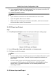
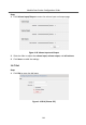
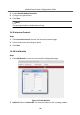
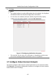
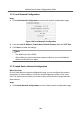
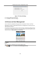
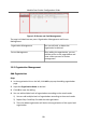
Table Of Contents
- Legal Information
- Symbol Conventions
- Regulatory Information
- 1 Device Configuration
- 2 Video Intercom Operation

3) Select network interface as interface type. Enter the elevator controller's IP
address, port No., user name, and password.
4) Enable the elevator control.
Note
•
Up to 4 elevator controllers can be connected to one door staon.
•
Up to 10 negave oors can be added.
•
Make sure the interface types of elevator controllers, which are connected
to the same door staon, are consistent.
1.6.5 I/O Input and Output
Steps
1.
Click I/O Input and Output to enter the I/O input and output sengs page.
Figure 1-17 I/O Input and Output
2.
Select I/O input No., input mode, output No., and output mode.
3.
Click Save to enable the sengs.
Note
•
For door staon, there are 4 I/O input terminals. By default, Terminal 1 and 2
correspond to Door Status. Terminal 3 and 4 correspond to interfaces of
Door Switch.
•
For door staon, there are 2 I/O Output Terminals. Terminal 1 and 2
correspond to DOOR interfaces (NO1/COM/NC1; NO2/COM/NC2) of door
staon. Door 1 is enabled by default. You can enable/disable IO Out
according to needs.
1.6.6 Volume Input and Output
Module Door Staon Conguraon Guide
13