
User Manual
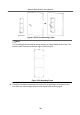
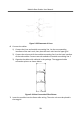
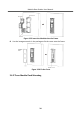
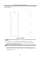
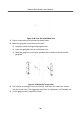
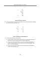
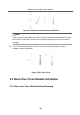
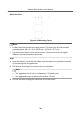
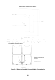
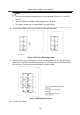
Table Of Contents
- Legal Information
- Symbol Conventions
- Regulatory Information
- 1 Terminal and Wiring
- 2 Installation
- 3 Activation
- 4 Remote Configuration via Web
- 4.1 Live View
- 4.2 User Management
- 4.3 Number Settings
- 4.4 Device Management
- 4.5 Parameters Settings
- 5 Configuration via Client Software
- A. Communication Matrix and Device Command

Note
•
There are 6 module-connecng lines in the package: 190 mm × 4 and 400
mm × 2.
•
Take the 400 mm module-connecng line for this step.
•
The green-yellow line in the package is for grounding.
6.
Fix the mounng frame onto the wall with 8 expansion bolts.
Figure 2-47 Fix the Mounng Frame
7.
Pass the main unit connecng line across the thread hole to the top grid of the
le frame. Thread the module-connecng line (190 mm) across the thread hole
of the frame. The lines should be placed as shown below.
Figure 2-48 Placement of Lines
8.
Connect the cables.
Module Door
Staon User Manual
41