
User Manual
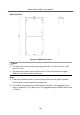
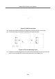
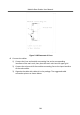
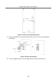
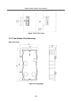
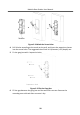
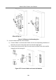
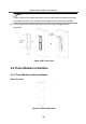
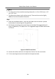
Table Of Contents
- Legal Information
- Symbol Conventions
- Regulatory Information
- 1 Terminal and Wiring
- 2 Installation
- 3 Activation
- 4 Remote Configuration via Web
- 4.1 Live View
- 4.2 User Management
- 4.3 Number Settings
- 4.4 Device Management
- 4.5 Parameters Settings
- 5 Configuration via Client Software
- A. Communication Matrix and Device Command

Figure 2-16 Drill Screw Holes
3.
Remove the scker and insert the expansion sleeves into the screw holes.
4.
Fix the mounng frame onto the wall with 4 expansion bolts.
Figure 2-17 Fix the Mounng Frame
5.
Thread the module-connecng line across the thread hole of the frame. Pass the
main unit connecng lines across the thread hole to the upper grid.
Module Door
Staon User Manual
23