
User Manual
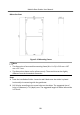
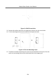
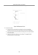
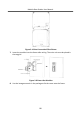
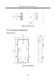
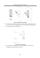
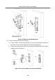
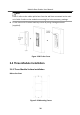
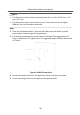
Table Of Contents
- Legal Information
- Symbol Conventions
- Regulatory Information
- 1 Terminal and Wiring
- 2 Installation
- 3 Activation
- 4 Remote Configuration via Web
- 4.1 Live View
- 4.2 User Management
- 4.3 Number Settings
- 4.4 Device Management
- 4.5 Parameters Settings
- 5 Configuration via Client Software
- A. Communication Matrix and Device Command

Figure 2-24 Mark the Screw Holes
4.
Drill 4 holes according to the marks on the wall, and insert the expansion sleeves
into the screw holes. The suggested size of hole is 6 (diameter) × 45 (depth) mm.
5.
Fix the gang box with 4 expansion bolts.
Figure 2-25 Fix the Gang Box
6.
Fill the gap between the gang box and the wall with concrete. Remove the
mounng ears with tool aer concrete is dry.
Module Door
Staon User Manual
28