
User Manual
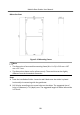
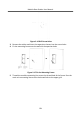
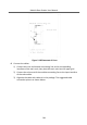
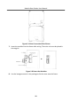
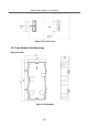
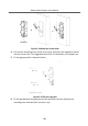
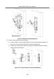
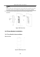
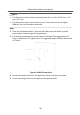
Table Of Contents
- Legal Information
- Symbol Conventions
- Regulatory Information
- 1 Terminal and Wiring
- 2 Installation
- 3 Activation
- 4 Remote Configuration via Web
- 4.1 Live View
- 4.2 User Management
- 4.3 Number Settings
- 4.4 Device Management
- 4.5 Parameters Settings
- 5 Configuration via Client Software
- A. Communication Matrix and Device Command

Note
The dimension of two-module gang box is: 237 (W) × 134 (H) × 56 (D) mm. The
dimension is for reference only.
Steps
1.
Drill the installaon hole, and pull the cable out.
Note
•
The suggested dimension of installaon hole is 220 (W) × 108 (H) × 45.5 (D)
mm.
•
The suggested length of cables le outside is 270 mm.
Figure 2-23 Drill the Installaon Hole
2.
Select a cable entry and remove the
plasc sheet.
3.
Mark the gang box screw holes on the hole.
1) Routs the cables through the gang box hole.
2) Insert the gang box into the installaon hole.
3) Mark the gang box screw holes'
posion with a marker, and take out the
gang box.
Module Door
Staon User Manual
27