
User Manual
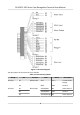
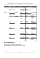
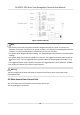
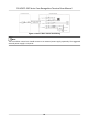

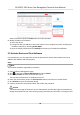
Table Of Contents
- Legal Information
- Symbol Conventions
- Regulatory Information
- Safety Instruction
- Available Models
- Chapter 1 Overview
- Chapter 2 Appearance
- Chapter 3 Installation
- Chapter 4 Wiring
- Chapter 5 Activation
- Chapter 6 Quick Operation
- Chapter 7 Basic Operation
- Chapter 8 Operation via Web Browser
- 8.1 Login
- 8.2 Live View
- 8.3 Person Management
- 8.4 Search Event
- 8.5 Configuration
- 8.5.1 Set Local Parameters
- 8.5.2 View Device Information
- 8.5.3 Set Time
- 8.5.4 Set DST
- 8.5.5 View Open Source Software License
- 8.5.6 Upgrade and Maintenance
- 8.5.7 Log Query
- 8.5.8 Security Mode Settings
- 8.5.9 Certificate Management
- 8.5.10 Change Administrator's Password
- 8.5.11 View Device Arming/Disarming Information
- 8.5.12 Network Settings
- 8.5.13 Set Video and Audio Parameters
- 8.5.14 Customize Audio Content
- 8.5.15 Set Image Parameters
- 8.5.16 Set Supplement Light Brightness
- 8.5.17 Time and Attendance Settings
- 8.5.18 Set Video Intercom Parameters
- 8.5.19 Configure SIP Parameters
- 8.5.20 Access Control Settings
- 8.5.21 Set Biometric Parameters
- 8.5.22 Set Notice Publication
- 8.5.23 Temperature Measurement Settings
- Chapter 9 Client Software Configuration
- 9.1 Configuration Flow of Client Software
- 9.2 Device Management
- 9.3 Group Management
- 9.4 Person Management
- 9.5 Configure Schedule and Template
- 9.6 Set Access Group to Assign Access Authorization to Persons
- 9.7 Configure Advanced Functions
- 9.8 Door Control
- Appendix A. Tips When Collecting/Comparing Face Picture
- Appendix B. Tips for Installation Environment
- Appendix C. Dimension

Group No. Funcon Color Name Descripon
B4 Alarm Output Yellow/Purple NC Alarm Output
Wiring
B5 Yellow/Brown COM
B6 Yellow/Red NO
Group C C1 RS-485 Yellow 485+ RS-485 Wiring
C2 Blue 485-
C3 Black GND Ground
C4 Wiegand Green W0 Wiegand
Wiring 0
C5 White W1 Wiegand
Wiring 1
C6 Brown WG_OK Wiegand
Authencated
C7 Orange WG_ERR Wiegand
Authencaon
Failed
C8 Purple BUZZER Buzzer Wiring
C9 Gray TAMPER Tampering
Alarm Wiring
Group D D1 Door Lock White/Purple NC Lock Wiring
(NC)
D2 White/Yellow COM Common
D3 White/Red NO Lock Wiring
(NO)
D4 Yellow/Green SENSOR Door Contact
D5 Yellow/Gray BTN Exit Door
Wiring
4.2 Wire Normal Device
You can connect the terminal with normal peripherals.
The wiring diagram without secure door control unit is as follows.
DS-K5671-3XF Series Face Recognion Terminal User Manual
10