
User Manual
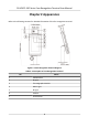

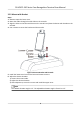
Table Of Contents
- Legal Information
- Symbol Conventions
- Regulatory Information
- Safety Instruction
- Available Models
- Chapter 1 Overview
- Chapter 2 Appearance
- Chapter 3 Installation
- Chapter 4 Wiring
- Chapter 5 Activation
- Chapter 6 Quick Operation
- Chapter 7 Basic Operation
- Chapter 8 Operation via Web Browser
- 8.1 Login
- 8.2 Live View
- 8.3 Person Management
- 8.4 Search Event
- 8.5 Configuration
- 8.5.1 Set Local Parameters
- 8.5.2 View Device Information
- 8.5.3 Set Time
- 8.5.4 Set DST
- 8.5.5 View Open Source Software License
- 8.5.6 Upgrade and Maintenance
- 8.5.7 Log Query
- 8.5.8 Security Mode Settings
- 8.5.9 Certificate Management
- 8.5.10 Change Administrator's Password
- 8.5.11 View Device Arming/Disarming Information
- 8.5.12 Network Settings
- 8.5.13 Set Video and Audio Parameters
- 8.5.14 Customize Audio Content
- 8.5.15 Set Image Parameters
- 8.5.16 Set Supplement Light Brightness
- 8.5.17 Time and Attendance Settings
- 8.5.18 Set Video Intercom Parameters
- 8.5.19 Configure SIP Parameters
- 8.5.20 Access Control Settings
- 8.5.21 Set Biometric Parameters
- 8.5.22 Set Notice Publication
- 8.5.23 Temperature Measurement Settings
- Chapter 9 Client Software Configuration
- 9.1 Configuration Flow of Client Software
- 9.2 Device Management
- 9.3 Group Management
- 9.4 Person Management
- 9.5 Configure Schedule and Template
- 9.6 Set Access Group to Assign Access Authorization to Persons
- 9.7 Configure Advanced Functions
- 9.8 Door Control
- Appendix A. Tips When Collecting/Comparing Face Picture
- Appendix B. Tips for Installation Environment
- Appendix C. Dimension

3.2.2 Mount with Bracket
Steps
1. Rotate to open the lower cover.
2. Route the cables through the cable hole on the
turnsle.
3. Align the holes on the base with those on the
turnsle and place the device with bracket on the
turnsle.
4. Use 4 screws to secure the bracket and the turnsle.
Figure 3-3 Secure Bracket and Turnsle
5. Install the lower cover back on the base and rotate to secure.
6. Adjust the device elevaon.
1) Loosen the screws inside.
2) Adjust the device elevaon.
3) Aer adjustment, secure the screws and install the upper cover.
Note
The default elevaon angle is 15°. The adjustable elevaon angle is from 0° to 15°.
DS-K5671-3XF Series Face Recognion Terminal User Manual
6