
User Manual
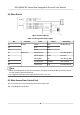
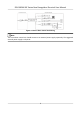
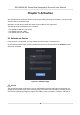
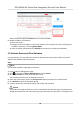

Table Of Contents
- Legal Information
- Symbol Conventions
- Regulatory Information
- Safety Instruction
- Available Models
- Chapter 1 Overview
- Chapter 2 Appearance
- Chapter 3 Installation
- Chapter 4 Wiring
- Chapter 5 Activation
- Chapter 6 Basic Operation
- 6.1 Set Application Mode
- 6.2 Login
- 6.3 Communication Settings
- 6.4 User Management
- 6.5 Temperature Measurement
- 6.6 Import and Export Data
- 6.7 Identity Authentication
- 6.8 System Settings
- 6.9 Set Access Control Parameters
- 6.10 Maintenance
- 6.11 Time and Attendance Status Settings
- 6.12 View System Information
- 6.13 Video Intercom
- Chapter 7 Client Software Configuration
- 7.1 Configuration Flow of Client Software
- 7.2 Device Management
- 7.3 Group Management
- 7.4 Person Management
- 7.4.1 Add Organization
- 7.4.2 Configure Basic Information
- 7.4.3 Issue a Card by Local Mode
- 7.4.4 Upload a Face Photo from Local PC
- 7.4.5 Take a Photo via Client
- 7.4.6 Collect Face via Access Control Device
- 7.4.7 Configure Access Control Information
- 7.4.8 Customize Person Information
- 7.4.9 Configure Resident Information
- 7.4.10 Configure Additional Information
- 7.4.11 Import and Export Person Identify Information
- 7.4.12 Import Person Information
- 7.4.13 Import Person Pictures
- 7.4.14 Export Person Information
- 7.4.15 Export Person Pictures
- 7.4.16 Get Person Information from Access Control Device
- 7.4.17 Move Persons to Another Organization
- 7.4.18 Issue Cards to Persons in Batch
- 7.4.19 Report Card Loss
- 7.4.20 Set Card Issuing Parameters
- 7.5 Configure Schedule and Template
- 7.6 Set Access Group to Assign Access Authorization to Persons
- 7.7 Configure Advanced Functions
- 7.7.1 Configure Device Parameters
- 7.7.2 Configure Remaining Open/Closed
- 7.7.3 Configure Multi-Factor Authentication
- 7.7.4 Configure Card Reader Authentication Mode and Schedule
- 7.7.5 Configure First Person In
- 7.7.6 Configure Anti-Passback
- 7.7.7 Configure Device Parameters
- 7.8 Configure Linkage Actions for Access Control
- 7.9 Door Control
- 7.10 Event Center
- 7.11 Time and Attendance
- 7.12 Remote Configuration (Web)
- 7.12.1 View Device Information
- 7.12.2 Change Device Password
- 7.12.3 Time Management
- 7.12.4 System Maintenance
- 7.12.5 Configure RS-485 Parameters
- 7.12.6 Security Mode Settings
- 7.12.7 Network Parameters Settings
- 7.12.8 Report Strategy Settings
- 7.12.9 Network Center Parameters Settings
- 7.12.10 Configure SIP Parameters
- 7.12.11 Set Relay Parameters
- 7.12.12 Set Access Control Parameters
- 7.12.13 Set Face Recognition Terminal Parameters
- 7.12.14 Configure Face Picture Parameters
- 7.12.15 Configure Supplement Light Parameters
- 7.12.16 Set Device No.
- 7.12.17 Configure Video and Audio Parameters
- 7.12.18 Configure Volume Input or Output
- 7.12.19 Operate Relay
- 7.12.20 View Relay Status
- Appendix A. Tips When Collecting/Comparing Face Picture
- Appendix B. Tips for Installation Environment
- Appendix C. Dimension

4.2 Wire Device
Figure 4-2 Device Wiring
Table 4-1 Wiring Terminal Descripon
No. Funcon Color Name Descripon
C1 RS-485 Yellow 485+ RS-485 Wiring
C2 Blue 485-
C3 Black GND
D1 Door Lock White/Purple NC Lock Wiring (NC)
D2 White/Yellow COM Common
D3 White/Red NO Lock Wiring (NO)
D4 Yellow/Green SENSOR Door Contact
D5 Yellow/Gray BTN Exit Door Wiring
Note
• When
connecng door contact and exit buon, the device and the RS-485 card reader should
use the common ground connecon.
• The suggested external power supply for door lock is 12 V, 1 A.
4.3 Wire Secure Door Control Unit
You can connect the terminal with the secure door control unit.
The wiring diagram is as follows.
DS-K5604A-3XF Series Face Recognion Terminal User Manual
6