
User Manual
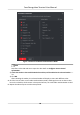
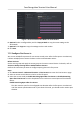
Table Of Contents
- Legal Information
- Symbol Conventions
- Regulatory Information
- Safety Instruction
- Available Models
- Chapter 1 Overview
- Chapter 2 Appearance
- Chapter 3 Installation
- Chapter 4 Wiring
- Chapter 5 Activation
- Chapter 6 Basic Operation
- 6.1 Set Application Mode
- 6.2 Login
- 6.3 Communication Settings
- 6.4 User Management
- 6.5 Temperature Measurement Settings
- 6.6 Import and Export Data
- 6.7 Identity Authentication
- 6.8 System Settings
- 6.9 Set Access Control Parameters
- 6.10 Maintenance
- 6.11 Time and Attendance Status Settings
- 6.12 View System Information
- 6.13 Video Intercom
- Chapter 7 Client Software Configuration
- 7.1 Configuration Flow of Client Software
- 7.2 Device Management
- 7.3 Group Management
- 7.4 Person Management
- 7.4.1 Add Organization
- 7.4.2 Configure Basic Information
- 7.4.3 Issue a Card by Local Mode
- 7.4.4 Upload a Face Photo from Local PC
- 7.4.5 Take a Photo via Client
- 7.4.6 Collect Face via Access Control Device
- 7.4.7 Configure Access Control Information
- 7.4.8 Customize Person Information
- 7.4.9 Configure Resident Information
- 7.4.10 Configure Additional Information
- 7.4.11 Import and Export Person Identify Information
- 7.4.12 Import Person Information
- 7.4.13 Import Person Pictures
- 7.4.14 Export Person Information
- 7.4.15 Export Person Pictures
- 7.4.16 Get Person Information from Access Control Device
- 7.4.17 Move Persons to Another Organization
- 7.4.18 Issue Cards to Persons in Batch
- 7.4.19 Report Card Loss
- 7.4.20 Set Card Issuing Parameters
- 7.5 Configure Schedule and Template
- 7.6 Set Access Group to Assign Access Authorization to Persons
- 7.7 Configure Advanced Functions
- 7.7.1 Configure Device Parameters
- 7.7.2 Configure Remaining Open/Closed
- 7.7.3 Configure Multi-Factor Authentication
- 7.7.4 Configure Card Reader Authentication Mode and Schedule
- 7.7.5 Configure First Person In
- 7.7.6 Configure Anti-Passback
- 7.7.7 Configure Device Parameters
- 7.8 Configure Linkage Actions for Access Control
- 7.9 Door Control
- 7.10 Event Center
- 7.11 Time and Attendance
- 7.12 Remote Configuration (Web)
- 7.12.1 View Device Information
- 7.12.2 Change Device Password
- 7.12.3 Time Management
- 7.12.4 System Maintenance
- 7.12.5 Configure RS-485 Parameters
- 7.12.6 Security Mode Settings
- 7.12.7 Network Parameters Settings
- 7.12.8 Report Strategy Settings
- 7.12.9 Network Center Parameters Settings
- 7.12.10 Configure SIP Parameters
- 7.12.11 Set Relay Parameters
- 7.12.12 Set Access Control Parameters
- 7.12.13 Set Face Recognition Terminal Parameters
- 7.12.14 Configure Face Picture Parameters
- 7.12.15 Configure Supplement Light Parameters
- 7.12.16 Set Device No.
- 7.12.17 Configure Video and Audio Parameters
- 7.12.18 Configure Volume Input or Output
- 7.12.19 Operate Relay
- 7.12.20 View Relay Status
- Appendix A. Tips When Collecting/Comparing Face Picture
- Appendix B. Tips for Installation Environment
- Appendix C. Dimension

Set Log Uploading Mode
You can set the mode for the device to upload logs via ISUP protocol.
Steps
1. Enter the Access Control module.
2. On the
navigaon bar on the le, enter Advanced Funcon → More Parameters .
3. Select an access control device in the device list and enter Network → Uploading Mode .
4. Select the center group from the drop-down list.
5. Check Enable to enable to set the uploading mode.
6. Select the uploading mode from the drop-down list.
-
Enable N1 or G1 for the main channel and the backup channel.
-
Select Close to disable the main channel or the backup channel
Note
The main channel and the backup channel cannot enable N1 or G1 at the same me.
7. Click Save.
Create ISUP Account in Wired
Communicaon Mode
You can set the account for ISUP protocol in wired communicaon mode. Then you can add
devices via ISUP protocol.
Steps
Note
This funcon should be supported by the device.
1. Enter the Access Control module.
2. On the navigaon bar on the le, enter Advanced Funcon → More Parameters .
3. Select an access control device in the device list and enter Network → Network Center .
4. Select the center group from the drop-down list.
5. Select the Address Type as IP Address or Domain Name.
6. Enter IP address or domain name according to the address type.
7. Enter the port number for the protocol.
Note
The port number of the wireless network and wired network should be consistent with the port
number of ISUP.
8. Select the Protocol Type as ISUP.
9. Set an account name for the network center.
10. Click Save.
Face Recognion Terminal User Manual
90