
User Manual
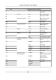
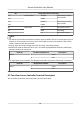
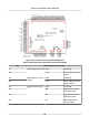

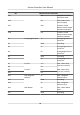
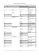
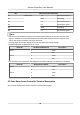
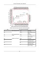
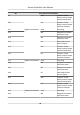
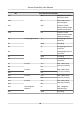
Table Of Contents
- Legal Information
- Available Model
- Regulatory Information
- Safety Instruction
- Chapter 1 Preventive and Cautionary Tips
- Chapter 2 Product Description
- Chapter 3 Main Board Description
- Chapter 4 Terminal Description
- Chapter 5 Terminal Wiring
- Chapter 6 Settings
- Chapter 7 Activation
- Chapter 8 Client Software Configuration
- 8.1 Operation on Client Software
- 8.1.1 Add Device
- 8.1.2 Select Application Scenario
- 8.1.3 Configure Other Parameters
- 8.1.4 Manage Organization
- 8.1.5 Manage Person Information
- 8.1.6 Configure Schedule and Template
- 8.1.7 Manage Permission
- 8.1.8 Configure Advanced Functions
- Configure Access Control Parameters
- Configure Individual Authentication
- Configure Card Reader Authentication Mode and Schedule
- Configure Multiple Authentication
- Configure Opening Door with First Card
- Configure Anti-Passback
- Configure Cross-Controller Anti-passing Back
- Configure Multi-door Interlocking
- Configure Authentication Password
- Configure Custom Wiegand Rule
- 8.1.9 Search Access Control Event
- 8.1.10 Configure Access Control Alarm Linkage
- 8.1.11 Manage Access Control Point Status
- 8.1.12 Control Door during Live View
- 8.1.13 Display Access Control Point on E-map
- 8.2 Remote Configuration (Web)
- 8.3 Time and Attendance
- 8.1 Operation on Client Software
- Appendix A. Tips for Scanning Fingerprint
- Appendix B. DIP Switch Description
- Appendix C. Custom Wiegand Rule Descriptions

No. Two-Door Access Controller
D1 Event Input C4 Event Alarm Input 4
D2 GND Grounding
D3 C3 Event Alarm Input 3
D4 C2 Event Alarm Input 2
D5 GND Grounding
D6 C1 Event Alarm Input 1
Note
• The alarm input hardware interface is normally open by default. So only the normally open
signal is allowed. It can be linked to the buzzer of the card reader and access controller, the
alarm relay output, and door relay open and close.
• Arming region alarm input linkage is only for the alarm relay output linkage.
• RS-485 card reader ID should be set as 1 to 8.
Door No. RS-485 Card Reader ID Descripon
Door 1 1 Enter
2 Exit
Door 2 3 Enter
4 Exit
• For two-door access controller, the Wiegand card reader and door's relaonship is as follows.
Door No. Wiegand Card Reader Descripon
Door 1 1 Enter
2 Exit
Door 2 3 Enter
4 Exit
4.3 Four-Door Access Controller Terminal Descripon
You can view the four-door access controller's terminal descripon.
Access Controller User Manual
16