
User Manual
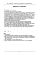
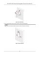
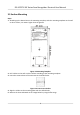
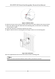
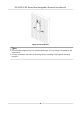
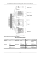
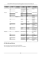
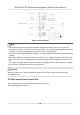
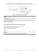
Table Of Contents
- Legal Information
- Symbol Conventions
- Regulatory Information
- Safety Instruction
- Available Models
- Chapter 1 Overview
- Chapter 2 Appearance
- Chapter 3 Installation
- Chapter 4 Wiring
- Chapter 5 Activation
- Chapter 6 Quick Operation
- Chapter 7 Basic Operation
- Chapter 8 Operation via Web Browser
- 8.1 Login
- 8.2 Live View
- 8.3 Person Management
- 8.4 Search Event
- 8.5 Configuration
- 8.5.1 Set Local Parameters
- 8.5.2 View Device Information
- 8.5.3 Set Time
- 8.5.4 Set DST
- 8.5.5 View Open Source Software License
- 8.5.6 Upgrade and Maintenance
- 8.5.7 Log Query
- 8.5.8 Security Mode Settings
- 8.5.9 Certificate Management
- 8.5.10 Change Administrator's Password
- 8.5.11 View Device Arming/Disarming Information
- 8.5.12 Network Settings
- 8.5.13 Set Video and Audio Parameters
- 8.5.14 Customize Audio Content
- 8.5.15 Set Image Parameters
- 8.5.16 Set Supplement Light Brightness
- 8.5.17 Time and Attendance Settings
- 8.5.18 Set Video Intercom Parameters
- 8.5.19 Access Control Settings
- 8.5.20 Set Biometric Parameters
- 8.5.21 Set Notice Publication
- 8.5.22 Temperature Measurement Settings
- Chapter 9 Client Software Configuration
- 9.1 Configuration Flow of Client Software
- 9.2 Device Management
- 9.3 Group Management
- 9.4 Person Management
- 9.4.1 Add Organization
- 9.4.2 Configure Basic Information
- 9.4.3 Issue a Card to One Person
- 9.4.4 Upload a Face Photo from Local PC
- 9.4.5 Take a Photo via Client
- 9.4.6 Collect Face via Access Control Device
- 9.4.7 Configure Access Control Information
- 9.4.8 Customize Person Information
- 9.4.9 Configure Resident Information
- 9.4.10 Configure Additional Information
- 9.4.11 Import and Export Person Identify Information
- 9.4.12 Import Person Information
- 9.4.13 Import Person Pictures
- 9.4.14 Export Person Information
- 9.4.15 Export Person Pictures
- 9.4.16 Delete Registered Pictures
- 9.4.17 Get Person Information from Access Control Device
- 9.4.18 Move Persons to Another Organization
- 9.4.19 Issue Cards to Persons in Batch
- 9.4.20 Report Card Loss
- 9.4.21 Set Card Issuing Parameters
- 9.5 Configure Schedule and Template
- 9.6 Set Access Group to Assign Access Authorization to Persons
- 9.7 Configure Advanced Functions
- 9.7.1 Configure Device Parameters
- 9.7.2 Configure Remaining Open/Closed
- 9.7.3 Configure Multi-Factor Authentication
- 9.7.4 Configure Card Reader Authentication Mode and Schedule
- 9.7.5 Configure First Person In
- 9.7.6 Configure Anti-Passback
- 9.7.7 Configure Device Parameters
- 9.8 Configure Linkage Actions for Access Control
- 9.9 Door Control
- 9.10 Event Center
- 9.11 Time and Attendance
- 9.12 System Configuration
- 9.13 Operation and Maintenance
- 9.14 Remote Configuration (Web)
- 9.14.1 View Device Information
- 9.14.2 Change Device Password
- 9.14.3 Time Management
- 9.14.4 System Maintenance
- 9.14.5 Configure RS-485 Parameters
- 9.14.6 Security Mode Settings
- 9.14.7 Network Parameters Settings
- 9.14.8 Report Strategy Settings
- 9.14.9 Network Center Parameters Settings
- 9.14.10 Configure SIP Parameters
- 9.14.11 Set Relay Parameters
- 9.14.12 Set Access Control Parameters
- 9.14.13 Set Face Recognition Terminal Parameters
- 9.14.14 Configure Face Picture Parameters
- 9.14.15 Configure Supplement Light Parameters
- 9.14.16 Set Device No.
- 9.14.17 Configure Video and Audio Parameters
- 9.14.18 Configure Volume Input or Output
- 9.14.19 Operate Relay
- 9.14.20 View Relay Status
- Appendix A. Tips When Collecting/Comparing Face Picture
- Appendix B. Tips for Installation Environment
- Appendix C. Dimension

Figure 3-5 Remove Sheet
6. Remove the two screws on the rear panel and remove the sheet to display the wiring terminals.
7. Route the cable through the cable hole of the
mounng plate, and connect to corresponding
external devices' cables.
8. Install the sheet back to the device with the two screws.
9. Align the device with the
mounng plate and hang the device on the mounng plate.
Figure 3-6 Install Device
10. Use 2 supplied M4 screws to secure the device and the mounng plate.
Note
When the screw's head is beneath the device surface, the device is secured.
DS-K1T671-3XF Series Face Recognion Terminal User Manual
8