
Users Manual

• Do not wire the device to the electric supply directly.
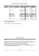
• If the interface for network connecon is too large, you can use the supplied cable as shown
belo
w.
Figure 4-2 Cable Diagram
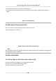
4.3 Wire Secure Door Control Unit
You can connect the terminal with the secure door control unit.
The wiring diagr
am is as follows.
Figure 4-3 Secure Door Control Unit Wiring
Note
The secure door control unit should connect to an external power supply separately. The suggested
e
xternal power supply is 12V, 0.5A.
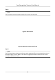
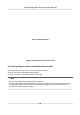
4.4 Wire Fire Module
4.4.1 Wiring Diagram of Door Open When Powering O
Lock Type: Anode Lock,
Magnec Lock, and Electric Bolt (NO)
Security Type: Door Open When Powering O
Scenario: Installed in Fire Engine Access
Face Recognion Terminal User Manual
20