
Users Manual


Chapter 4 Wiring
The device supports connecng to the RS-485 terminal, the door lock, the exit buon, the alarm
output/input devices, the Wiegand card reader, the access controller, and the power supply. You
can wire the peripherals according to the descripons below.
If connect the Wiegand card reader with the access controller, the face recognion terminal can
transmit the authencaon informaon to the access controller and the access controller can
judge whether to open the door or not.
Note
• If the cable size is 18 AWG, you should use a 12 V switched-mode power supply. And the
dis
tance between the power supply and the device should be no more than 20 m.
• If the cable size is 15 AWG, you should use a 12 V switched-mode power supply. And the
distance between the power supply and the device should be no more than 30 m.
• If the cable size is 12 AWG, you should use a 12 V switched-mode power supply. And the
distance between the power supply and the device should be no more than 40 m.
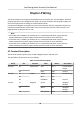
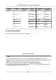
4.1 Terminal
Descripon
The terminals contains power input, RS-485, Wiegand output, and door lock.
The
descripons of the terminals are as follows:
Table 4-1 Terminal Descripons
Group No. Funcon Color Name Descripon
Group A A1 Power Input Red +12 V 12 VDC Power
Supply
A2 Black GND Ground
Group B B1 RS-485 Yellow 485+ RS-485 Wiring
B2 Blue 485-
B3 Red/Black GND Ground
Group C C1 Wiegand Green W0 Wiegand
Wiring 0
C2 White W1 Wiegand
Wiring 1
C3 White/Black GND Ground
Face Recognion Terminal User Manual
18