
Users Manual
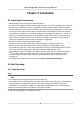
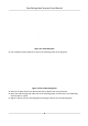
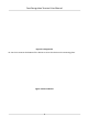
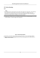
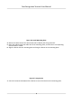
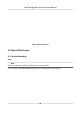
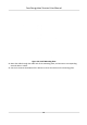
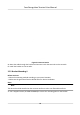
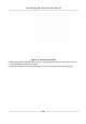
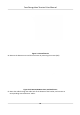

Figure 3-1 Install Gang Box
2. Use 4 supplied scr
ews (KA4×22) to secure the mounng plate on the gang box.
Figure 3-2 Secure Mounng Plate
3. R
emove the back sheet of the device with tools to display the wiring terminals.
4. Route the cable through the cable hole of the mounng plate, and connect to corresponding
external devices' cables.
5. Align the device with the mounng plate and hang the device on the mounng plate.
Face
Recognion Terminal User Manual
6