
User Manual


User Manual of Network Video Recorder User Manual
21
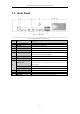
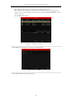
1.5 Rear Panel
Figure 1. 5 Rear Panel
Table 1. 5 Description of Rear Panel Interfaces
No.
Item
Description
1
LAN1/LAN2 Interface
2 RJ-45 10 /100 /1000 Mbps self-adaptive Ethernet interfaces provided.
2
LINE IN
RCA connector for audio input.
3
AUDIO OUT
2 RCA connectors for audio output.
4
HDMI1/HDMI2
HDMI video output connector.
5
VGA1/VGA2
DB9 connector for VGA output. Display local video output and menu.
6
USB 3.0 interface
Universal Serial Bus (USB) ports for additional devices such as USB
mouse and USB Hard Disk Drive (HDD).
7
RS-232 Interface
Connector for RS-232 devices.
8
eSATA
Connects external SATA HDD, CD/DVD-RM.
9
Controller Port
D+, D- pin connects to Ta, Tb pin of controller. For cascading devices,
the first NVR’s D+, D- pin should be connected with the D+, D- pin of
the next NVR.
ALARM IN
Connector for alarm input.
ALARM OUT
Connector for alarm output.
10
AC 100V ~ 240V
100V ~ 240 VAC power supply.
11
Power Switch
Switch for turning on/off the device.
12
GROUND
Ground (needs to be connected when NVR starts up).