
User Manual

Network Video Recorder User Manual
UM NVR v4.xx 111717NA 61
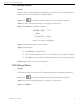
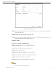
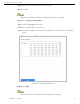
Figure 7-13 Pattern Configuration
Step 4 Select a pattern in the text field.
Step 5 Click Call to start the pattern.
Step 6 (Optional) Click Stop to stop the pattern.
7.3.7 Setting Linear Scan Limits
Before You Start
Make sure the connected IP camera supports the PTZ function and is properly
connected.
Purpose
Linear Scan trigger a scan in the horizontal direction in the predefined range.
This function is supported only by certain models.
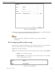
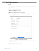
Step 1 Click on the quick settings toolbar of the PTZ camera’s Live View.
Step 2 The PTZ control panel displays on the right of the interface.
Step 3 Click the directional buttons to wheel the camera to the location of where you
want to set the limit, and click Left Limit or Right Limit to link the location to the
corresponding limit.
The speed dome linear scans from the left limit to the right limit, and you must set
the left limit on the left side of the right limit. Also, the angle from the left limit to
the right limit must be no more greater than 180°.
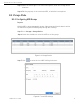
7.3.8 Calling Linear Scan
Before operating this function, make sure the connected camera supports linear
scan and is in HIKVISION protocol.