
User Manual

Network Video Recorder User Manual
UM NVR v4.xx 111717NA 23
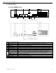
1.4 Rear Panel
1.4.1 DS-9600NI Series
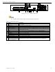
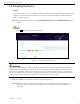
Figure 1-6 DS-9600NI-I8 Series
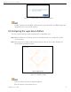
Figure 1-7 DS-9600NI-I16 Series
Table 1-6 Panel Description
No.
N
ame
Description
1
LAN1/LAN2 Interface
2 RJ
-
45 10/100/1000 Mbps self
-
adaptive Ethernet interfaces provided
2
LINE IN
RCA connector for audio input
3
AUDIO OUT
2 RCA connectors for audio output
4
HDMI1/HDMI2
HDMI video output connector
5
VGA1/VGA2
DB
-
9
connector for VGA output. Display local video output and menu.
6
USB 3.0 interface
Universal Serial Bus ports for
devices such as USB mouse
,
USB Hard Disk Drive (HDD)
7
RS
-
232 Interface
Connector for RS
-
232 devices
8
eSATA
Connects external SATA HDD, CD
/DVD
-
RM
9
Controller Port
D+, D
-
pin
s connect
to Ta, Tb pin
s
of controller. For cascading devices, the first
device
’s D+, D
-
pin should be connected
to
the D+, D
-
pin of the next
device
ALARM IN
Connector for alarm input
ALARM OUT
Connector for alarm
output
10
100 to 240 VAC
100 to 240 VAC power supply
11
Power Switch
Switch for turning on/off the device
12
GROUND
Ground (needs to be connected when
device
starts)