
User Manual
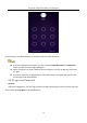
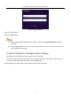

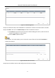


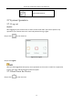


Table Of Contents
- Chapter 1 Introduction
- Chapter 2 Getting Started
- Chapter 3 Camera Management
- Chapter 4 Camera Settings
- Chapter 5 Live View
- Chapter 6 PTZ Control
- Chapter 7 Storage
- 7.1 Storage Device Management
- 7.2 Storage Mode
- 7.3 Recording Parameters
- 7.4 Configure Recording Schedule
- 7.5 Configure Continuous Recording
- 7.6 Configure Motion Detection Triggered Recording
- 7.7 Configure Event Triggered Recording
- 7.8 Configure Alarm Triggered Recording
- 7.9 Configure POS Event Triggered Recording
- 7.10 Configure Picture Capture
- 7.11 Configure Holiday Recording and Capture
- 7.12 Configure Redundant Recording and Capture
- Chapter 8 Disk Array
- Chapter 9 File Management
- Chapter 10 Playback
- Chapter 11 Event and Alarm Settings
- Chapter 12 VCA Event Alarm
- 12.1 Human Body Detection
- 12.2 Face Detection
- 12.3 Vehicle Detection
- 12.4 Line Crossing Detection
- 12.5 Intrusion Detection
- 12.6 Region Entrance Detection
- 12.7 Region Exiting Detection
- 12.8 Unattended Baggage Detection
- 12.9 Object Removal Detection
- 12.10 Audio Exception Detection
- 12.11 Sudden Scene Change Detection
- 12.12 Defocus Detection
- 12.13 PIR Alarm
- 12.14 Enable Smart Search
- Chapter 13 Smart Search
- Chapter 14 Human Body Detection
- Chapter 15 POS Configuration
- Chapter 16 Network Settings
- Chapter 17 Hot Spare Device Backup
- Chapter 18 System Maintenance
- Chapter 19 General System Settings
- Chapter 20 Appendix

Network Video Recorder User Manual
39
Step 6 (Optional) Click Continue to Add to continue to add other IP cameras.
3.1.2 Add the Automatically Searched Online IP Cameras
Step 1 On the Camera Management interface, click the Online Device panel to expand the Online
Device interface.
Step 2 Select the automatically searched online devices.
Step 3 Click Add.
If the IP camera to add has not been actiavated, you can activate it from the IP camera list on the
camera management interface.
3.2 Manage Cameras for PoE Device
This chapter is only applicable for the following models: DS-7700NXI-I/P/S series device.
Purpose:
The PoE interfaces enables the device system to pass electrical power safely, along with data, on
Ethernet cabling to the connected PoE cameras. Supported PoE camera number varies with device
model
If you disable the PoE interface, you can also connect to the online network cameras. And the PoE
interface supports the Plug-and-Play function.
For example, for iDS-7716NXI-I4/16P/8S, if you want to connect 8 network cameras via PoE
interfaces and 8 online cameras, you must disable 8 PoE interfaces in the Edit IP Camera menu.
Follow the steps to add network cameras for device supporting PoE function.
3.2.1 Add PoE Cameras
Step 1 Connect PoE cameras to device PoE ports with network cables.
Step 2 Go to Camera > Camera > IP Camera to view camera image and information.
3.2.2 Add Non-PoE IP Cameras
You can disable the PoE interface by selecting the manual while the current channel can be used as
a normal channel and the parameters can also be edited.
Step 1 Go to Camera > Camera > IP Camera.