Network Video Recorder Quick Start Guide
Network Video Recorder Quick Start Guide TABLE OF CONTENTS Chapter 1 Panels Description ..................................................................................................... 6 1.1 Front Panel ............................................................................................................................... 6 1.2 Rear Panel ................................................................................................................................ 7 1.2.
Network Video Recorder Quick Start Guide Quick Start Guide COPYRIGHT © 2018 Hangzhou Hikvision Digital Technology Co., Ltd. ALL RIGHTS RESERVED. Any and all information, including, among others, wordings, pictures, graphs are the properties of Hangzhou Hikvision Digital Technology Co., Ltd. or its subsidiaries (hereinafter referred to be “Hikvision”).
Network Video Recorder Quick Start Guide Regulatory Information FCC Information Please take attention that changes or modification not expressly approved by the party responsible for compliance could void the user’s authority to operate the equipment. FCC compliance: This equipment has been tested and found to comply with the limits for a Class A digital device, pursuant to part 15 of the FCC Rules.
Network Video Recorder Quick Start Guide Applicable Models This manual is applicable to the model listed in the following table. Series DS-7700NXI-I/S DS-7700NXI-I/P/S Model DS-7716NXI-I4/4S DS-7732NXI-I4/4S DS-7716NXI-I4/16P/4S DS-7732NXI-I4/16P/4S DS-7608NXI-I2/4S DS-7600NXI-I/S DS-7616NXI-I2/4S DS-7632NXI-I2/4S DS-7608NXI-I2/8P/4S DS-7600NXI-I/P/S DS-7616NXI-I2/16P/4S DS-7632NXI-I2/16P/4S Symbol Conventions The symbols that may be found in this document are defined as follows.
Network Video Recorder Quick Start Guide Safety Instructions Proper configuration of all passwords and other security settings is the responsibility of the installer and/or end-user. In the use of the product, you must be in strict compliance with the electrical safety regulations of the nation and region. Please refer to technical specifications for detailed information.
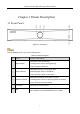
Network Video Recorder Quick Start Guide Chapter 1 Panels Description 1.1 Front Panel Figure 1-1 Front Panel The DS-7600NXI series only have one USB 2.0 port. Table 1-1 Panel Description No. Name Function Description Solid white: HDD is abnormal. 1 HDD indicator Flashing white: HDD is reading/writing. Unlit: No HDD is detected. Solid white: Device is running normally. 2 Power indicator Breathing light: Device is shutdown. Unlit: No power supply is connected.
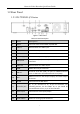
Network Video Recorder Quick Start Guide 1.2 Rear Panel 1.2.1 DS-7700NXI-I/S Series Figure 1-2 Rear Panel Table 1-2 Panel Description No. Name Description 1 eSATA Connects external SATA HDD, CD/DVD-RM. 2 Audio in RCA connector for audio input. 3 Video out CVBS video output. 4 RS-232 Connector for RS-232 device. 5 Power supply 100 to 240 VAC power supply 6 LAN1/LAN2 2 RJ-45 10/100/1000 Mbps self-adaptive Ethernet interfaces. 7 Audio out RCA connector for audio output.
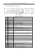
Network Video Recorder Quick Start Guide 1.2.2 DS-7700NXI-I/P/S Series Figure 1-3 Rear Panel Table 1-3 Panel Description No. Name Description 1 Video out CVBS video output. 2 eSATA Connects external SATA HDD, CD/DVD-RM. 3 RS-232 Connector for RS-232 device. 4 Audio in RCA connector for audio input. VGA DB9 connector for VGA output. Display local video output and menu. 6 Power supply 100 to 240 VAC power supply 7 PoE RJ-45 10/100 Mbps self-adaptive Ethernet interfaces.
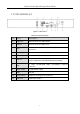
Network Video Recorder Quick Start Guide 1.2.3 DS-7600NXI-I/S Figure 1-4 Rear Panel Table 1-4 Panel Description No. Name Description 1 Audio out RCA connector for audio output. 2 Audio in RCA connector for audio input. VGA DB9 connector for VGA output. Display local video output and menu. 4 Alarm in/out Connector for alarm input/output. 5 HDMI HDMI video output connector. USB 3.0 Universal Serial Bus (USB) 3.0 port for additional device such as USB mouse and USB Hard Disk Drive (HDD).
Network Video Recorder Quick Start Guide 1.2.4 DS-7600NXI-I/P/S Figure 1-5 Rear Panel Table 1-5 Panel Description No. Name Description 1 PoE RJ-45 10/100 Mbps self-adaptive Ethernet interfaces. 2 Audio out RCA connector for audio output. 3 Audio in RCA connector for audio input. VGA DB9 connector for VGA output. Display local video output and menu. 5 Alarm in/out Connector for alarm input/output. 6 HDMI HDMI video output connector. USB 3.0 Universal Serial Bus (USB) 3.
Network Video Recorder Quick Start Guide Chapter 2 Installation and Connections 2.1 Installation During installation of the NVR: Use brackets for rack mounting. Ensure ample room for audio and video cables. When routing cables, ensure that the bend radius of the cables are no less than five times than its diameter. Connect the alarm cable. Allow at least 2cm (≈0.75-inch) of space between racks mounted devices. Ensure the NVR is grounded.
Network Video Recorder Quick Start Guide 1) 2) 3) 4) Connect one end of data cable to the device motherboard. Connect the other end of data cable to HDD. Connect one end of power cable to HDD. Connect the other end of power cable to the device motherboard. Figure 2-2 Connect Cables Step 3 Set the device up, match HDD screw threads with the reserved holes on the device bottom, and fix HDD with screws. Figure 2-3 Fix HDD to Device Bottom Step 4 (Optional) Repeat the steps above to install other HDDs.
Network Video Recorder Quick Start Guide Figure 2-4 Alarm Input Wiring 2.3.2 Alarm Output Wiring To connect to an alarm output (AC or DC load), use the following diagram: Figure 2-5 Alarm Output Wiring For DC load, the jumpers can be used within the limit of 12V/1A safely. To connect an AC load, jumpers should be left open (you must remove the jumper on the motherboard in the NVR). Use an external relay for safety (as shown in the figure above).
Network Video Recorder Quick Start Guide 2.3.4 Controller Connection Figure 2-6 Controller Connection To connect a controller to the NVR: Step 2 Disconnect pluggable block from the KB terminal block. Step 3 Unfasten stop screws from the KB D+, D- pluggable block, insert signal cables into slots and fasten stop screws. Ensure signal cables are in tight. Step 4 Connect Ta on controller to D+ on terminal block and Tb on controller to D- on terminal block. Fasten stop screws.
Network Video Recorder Quick Start Guide Bit Rate Storage Used 96K 42M 128K 56M 160K 70M 192K 84M 224K 98M 256K 112M 320K 140M 384K 168M 448K 196M 512K 225M 640K 281M 768K 337M 896K 393M 1024K 450M 1280K 562M 1536K 675M 1792K 787M 2048K 900M 4096K 1.8G 8192K 3.6G 16384K 7.2G Please note that supplied values for storage space used is just for reference. The storage values in the chart are estimated by formulas and may have some deviation from actual value.
Network Video Recorder Quick Start Guide Chapter 3 Menu Operation 3.1 Start up Your Device Proper startup and shutdown procedures are crucial to expanding the life of the NVR. To start your device: Step 1 Check the power supply is plugged into an electrical outlet. It is HIGHLY recommended that an Uninterruptible Power Supply (UPS) be used in conjunction with the device. The Power button on the front panel should be red, indicating the device is receiving the power.
Network Video Recorder Quick Start Guide We highly recommend you create a strong password of your own choosing (Using a minimum of 8 characters, including at least three of the following categories: upper case letters, lower case letters, numbers, and special characters.) in order to increase the security of your product. And we recommend you reset your password regularly, especially in the high security system, resetting the password monthly or weekly can better protect your product.
Network Video Recorder Quick Start Guide Figure 3-2 Draw the Pattern Connect at least 4 dots to draw the pattern. Each dot can be connected for once only. Step 3 Draw the same pattern again to confirm it. When the two patterns match, the pattern is configured successfully. If the two patterns are different, you must set the pattern again. 3.4 Log into the System Purpose If the device has logged out, you must log in the device before operating the menu and other functions.
Network Video Recorder Quick Start Guide Figure 3-3 Login Interface Step 3 Input Password. Step 4 Click Login to log in. In the Login dialog box, if you enter the wrong password 7 times, the current user account will be locked for 60 seconds. 3.5 Enter Wizard to Configure Quick Basic Settings The Setup Wizard can walk you through some important settings of the device. By default, the Setup Wizard starts once the device has loaded. Check the checkbox to enable Setup Wizard when device starts.
Network Video Recorder Quick Start Guide 3.6 Network Settings Purpose Network settings must be properly configured before you operate device over network. Step 1 Go to System > Network > TCP/IP. Figure 3-5 Network Settings Step 2 Select the General tab. Step 3 In the General Settings interface, you can configure the following settings: NIC Type, IPv4 Address, IPv4 Gateway, MTU and DNS Server.
Network Video Recorder Quick Start Guide Step 1 Click on the main menu bar to enter the Camera Management. Step 2 Click the Custom Add tab on the title bar to enter the Add IP Camera interface. Figure 3-6 Add IP Camera Step 3 Enter IP address, protocol, management port, and other information of the IP camera to add. Step 4 Enter the login user name and password of the IP camera. Step 5 Click Add to finish the adding of the IP camera.
Network Video Recorder Quick Start Guide Figure 3-7 Live View You can use the toolbar at the window bottom to realize the capture, instant playback, audio on/off, digital zoom, live view strategy, show information and start/stop recording, etc. 3.9 One-Touch RAID Configuration Purpose: The device supports the RAID storage function. Through one-touch configuration, you can quickly create the disk array. By default, the array type to be created is RAID 5. Before you start: Enable RAID function.
Network Video Recorder Quick Start Guide If you install 4 or more HDDs, a hot spare disk for array rebuilding will be created. Step 4 A message box will pop up when the array creation is completed, click OK on it. Step 5 Optionally, the device will automatically initialize the created array. Go to Storage > RAID Setup > Array view the information of created arrray. 3.10 Recording Settings Before you start: Make sure that the disk has already been installed or added.
Network Video Recorder Quick Start Guide Figure 3-9 Record Schedule Step 5 Select a day and click-and-drag the mouse on the time bar to set the record schedule. Step 6 Click Apply to save the settings. 3.11 Playback The recorded video files on the hard disk can be played back in the following modes: instant playback, all-day playback for the specified channel, and playback by normal/important/custom/event/smart/tag/sub-periods/external file search.
Network Video Recorder Quick Start Guide Figure 3-10 Playback Interface Step 4 Select the channel(s) to or execute simultaneous playback of multiple channels.
Network Video Recorder Quick Start Guide Chapter 4 Access by Web Browser You shall acknowledge that the use of the product with Internet access might be under network security risks. For avoidance of any network attacks and information leakage, please strengthen your own protection. If the product does not work properly, please contact with your dealer or the nearest service center. Purpose: You can get access to the device via web browser.
Network Video Recorder Quick Start Guide If the device is already activated, enter the user name and password in the login interface, and click the Login button. Figure 4-2 Login Step 3 Install the plug-in before viewing the live video and managing the camera. Please follow the installation prompts to install the plug-in. You may have to close the web browser to finish the installation of the plug-in.
Network Video Recorder Quick Start Guide UD10499B 28