
User's Manual
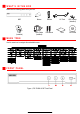
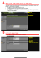


F R O N T P A N E L ( c o n t i n u e d )
No.
Item
Description
1.
Power Switch
Turns unit on/off.
Po
wer:
GREEN
when system has power
and is turned on.
2
.
HDD
BLINKS
RED
when data is bei
ng read from or written to HDD
3. TX/RX
GREEN
when
connected to
network
,
BLINKS
GREEN
when there is network
traffic
4.
USB Ports
Connects
USB
mouse or USB flash memory
devices
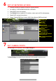
R E A R P A N E L
Figure 2, DS-7616NI-I2/16P Rear Panel
No.
Item
Description
1
Audio In
RCA
connector
s
2
Alarm I/O
Alarm
input/output connectors
3
Alarm I/O Legend
Alarm I/O labels
4
LAN
Connector for LAN (Local Area Network)
5
Grounding Screw
Ground
(
WARNING
:
needs to be connected when NVR starts up)
6
Power Input
100 to 240 VAC
7
Power Switch
Switch for turning
device
on/off
8
Network Interfaces w/PoE
IP camera inputs and PoE outputs
(DS
-
7608NI
-
I2/8P has eight PoE ports)
9
Audio Out
RCA
connector
s
10
VGA Out
DB
-
15 connector for VGA output
(d
isplay local video output and
menu
)
11
HDMI Out
HDMI video output
connector
12
USB
USB
3.0
port for additional
devices
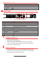
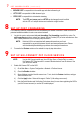
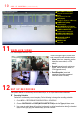
1 C O N N E C T D E V I C E S
1. Connect AC power cord to the NVR.
2. Connect NVR to LAN using Cat 5e cable.
3. Connect video monitor(s) to NVR using HDMI and/or VGA cables, as appropriate.
4. Connect mouse to USB port (wireless mouse can be used in lieu of included mouse).
5. Connect to audio I/O using RCA connectors.
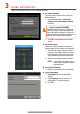
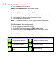
2 S T A R T T H E N V R
1. Plug AC power cord into 110 to 240 VAC outlet (surge suppressor is recommended).
2. Turn power switch on. Power indicator LED will turn GREEN to indicate unit is starting.
3. After startup, power indicator LED will remain GREEN.