
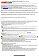
Quick Start Guide
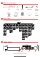
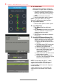

F R O N T P A N E L ( c o n t i n u e d )
No.
Description
1 Indicator LEDs
Power
Green when power switch on real panel is on, red when power switch is off
Ready
Green when DVR is functioning properly
Status
N/A
Alarm
Red when a sensor alarm is detected
HDD
Flickers red
when data is being read from or written to HDD
TX/RX
Flickers green when network connection is functioning properly
2
On/Off Switch
Starts up or shuts down the DVR processes
3
USB
USB ports for additional devices such as USB mouse and USB Hard Disk
Drive (HDD)
4
DVD
-
RW Bay
Slot to install DVD
-
RW drive
5
IR Sensor
Receives remote control signal
6
Direction Buttons
N
avigate
s
between different fields and items in menus
7
Enter Key
Accepts input
8 Buttons
Numbers
Enters numeric values into fields
Functions
Controls DVR functions
^
Switches between
composite key
numer
als (no light)
and
functions (red light)
9
Jog Dial
Use to scrub video forward/backward quickly
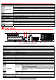
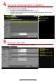
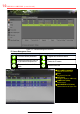
R E A R P A N E L
Figure 2, DS-7316HUHI-F4/N Rear Panel
No.
Item
Description
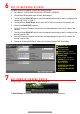
1
AUDIO IN
RCA connector
2
AUDIO OUT
RCA connector
3
LINE IN
RCA connector
4
VIDEO OUT
BNC interface
5
HDMI 2
HDMI video output connector
6
RS
-
232
DB
-
9 serial interface
7
eSATA
Connector for external eSATA storage
8
Power In
100
to 240 VAC power
9
VIDEO IN
BNC interface for HD
-
TVI, and analog video input
10
USB
USB port for additional devices
11
HDMI 1
HDMI video output connector
12
VGA
DB
-
15 connector for VGA output, displays local video output and menu
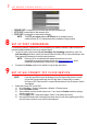
13
LAN 1 AND 2
Connectors for network
14
Connectors
ALARM IN
Alarm inputs
RS-485
Connector for RS
-
485 devices: T+ and T
-
pins connect to R+ and R
-
pins of PTZ receiver respectively
D+, D
-
pins connects to Ta, Tb pins of controller (for cascading
devices, the first DVR’s D+, D- pins connects to the D+, D- pins of the
next DVR)
KB
Keyboard connector
ALARM
OUT
Alarm outputs
15
GROUND
Grounding screw
16
POWER SWITCH
On/off switch