
User Manual

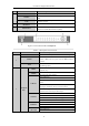


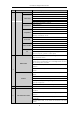
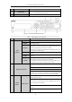
Table Of Contents
- Product Key Features
- Chapter 1 Introduction
- Chapter 2 Getting Started
- Chapter 3 Live View
- Chapter 4 PTZ Controls
- Chapter 5 Recording Settings
- 5.1 Configuring Recording Parameters
- 5.2 Configuring Record Schedule
- 5.3 Configuring Motion Detection Record
- 5.4 Configuring Alarm Triggered Record
- 5.5 Configuring VCA Record
- 5.6 Configuring Manual Record
- 5.7 Configuring Holiday Record
- 5.8 Configuring Redundant Recording
- 5.9 Configuring HDD Group for Recording
- 5.10 Files Protection
- Chapter 6 Playback
- Chapter 7 Backup
- Chapter 8 Alarm Settings
- Chapter 9 Network Settings
- Chapter 10 HDD Management
- Chapter 11 Camera Settings
- Chapter 12 DVR Management and Maintenance
- Chapter 13 Others
- Appendix

User Manual of Digital Video Recorder
19
No.
Name
Function Description
7
USB Interface
Universal Serial Bus (USB) ports for additional devices such as USB
mouse and USB Hard Disk Drive (HDD).
8
IR Receiver
Receiver for IR remote control.
Figure 1. 6 Front Panel of DS-8100-SH
Table 1. 5 Description of Front Panel
No.
Name
Function Description
1
Status
Indicators
ALARM
Alarm indicator turns red when a sensor alarm is detected.
READY
Ready indicator is normally blue, indicating that the DVR is
functioning properly.
STATUS
Indicator turns blue when DVR is controlled by an IR remote.
Indicator turns red when controlled by a keyboard and orange when
IR remote and keyboard is used at the same time.
Indicator does not light when the DVR is controlled by the IR remote
control with the address of 255.
HDD
HDD indicator blinks in red when data is being read from or written
to HDD.
Tx/Rx
Tx/Rx indictor blinks in blue when network connection is functioning
properly.
GUARD
Indicator turns blue when the device is armed;
Indicator does not light when the device is disarmed;
The arm/disarm state can be initiated by pressing and holding on the
ESC button for more than 3 seconds in live view mode.
2
Alphanumeric Buttons
Switch to the corresponding channel in Live view or PTZ Control
mode.
Input numbers and characters in Edit mode.
Switch between different channels in Playback mode.
The light of the button is blue when the corresponding channel is
recording; it is red when the channel is in network transmission
status; it is pink when the channel is recording and transmitting.
3
Control
Buttons
DIRECTION
The DIRECTION buttons are used to navigate between different
fields and items in menus.
In the Playback mode, the Up and Down button is used to speed up
and slow down recorded video. The Left and Right button will select
the next and previous record files.
In Live View mode, these buttons can be used to cycle through
channels.
In PTZ control mode, it can control the movement of the PTZ
camera.