
Operation Manual


User Manual of Digital Video Recorder
28
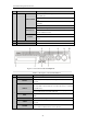
1.5 Rear Panel
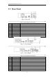
Figure 1. 10 DS-7100
Table 1. 10 Description of Front Panel
No.
Item
Description
1
VIDEO IN
BNC interface for TVI and analog video input.
2
HDMI
HDMI video output connector.
3
VGA
DB15 connector for VGA output. Display local video output and menu.
4
AUDIO OUT
RCA connector.
5
AUDIO IN
RCA connector.
6
Network Interface
Connector for network
7
USB Port
Universal Serial Bus (USB) port for additional devices.
8
GND
Ground
9
Power Supply
DC 12V power supply.
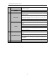
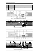
Figure 1. 11 DS-7200HGHI
Figure 1. 12 DS-7200HQHI
Table 1. 11 Description of Front Panel
No.
Item
Description
1
VIDEO IN
BNC interface for TVI and analog video input.
2
AUDIO IN
RCA connector
3
AUDIO OUT
RCA connector
4
VGA
DB15 connector for VGA output. Display local video output and menu.
5
HDMI
HDMI video output connector.
6
USB Port
Universal Serial Bus (USB) port for additional devices.
7
Network Interface
Connector for network
8
RS-485 Interface
Connector for RS-485 devices.
9
Power Supply
12V DC power supply.