
Quick Start Guide
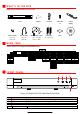
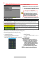

R E A R P A N E L S ( c o n t i n u e d )
No.
Item
Description
1
VIDEO
IN
BNC connector for video
input
.
/P Models Only: Power-over-Coax (PoC) function provides power to PoC enabled cameras. Up to
984 ft (300 m) range when using AF RG6.
2
ALARM IN
Connectors for alarm inputs
3
AUDIO OUT
RCA connectors for audio output
4
VGA
DB
-
15 connector for VGA output
to display local video output and men
5
HDMI
HDMI video output connector
6
USB Interface
Connect to USB mouse or USB flash memory devices
7
LAN
Connector for LAN (Local Area Network)
8 RS-485
Connector for RS
-
485 devices: T+ and T
-
pins connect to R+
and R
-
pins of PTZ receiver
respectively
D+, D
-
pin connects to Ta, Tb pin of controller (for cascading devices, the first DVR’s D+, D
-
pin
should be connected with the D+, D
-
pin of the next DVR)
9
Power Input
P
ower
supply
connect
ion
10
Power Switch
Switch for turning device on/off
11
Ground
Connect before powering up
12
Video
Out
BNC connector for
CVBS
signal
out
13
Alarm I/O
Alarm input and output connectors
14
Alarm I/O Legend
Alarm input and output labels
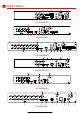
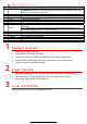
1 C O N N E C T D E V I C E S
1. Connect power supply to the DVR.
2. Connect DVR to LAN using Cat 5e cable.
3. Connect video monitor(s) to DVR using HDMI and/or VGA cables, as appropriate.
4. Connect mouse to USB port (wireless mouse can be used in lieu of included mouse).
5. Connect to audio I/O using RCA connectors.
2 S T A R T T H E D V R
1. Plug power supply plug into 110 to 240 VAC outlet (surge suppressor is recommended).
2. Turn power switch on. Power indicator LED will turn on to indicate unit is starting.
3. After startup, power indicator LED will remain on.
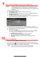
3 L O C A L A C T I V A T I O N
System access requires a secure, user-assigned password.