
User Manual
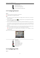
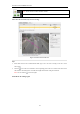
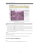
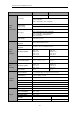
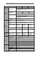
Table Of Contents
- CHAPTER 1 Introduction
- CHAPTER 2 Panels and Connections
- CHAPTER 3 Initial Network Parameters Configuration
- CHAPTER 4 Decoder Configuration and Operation by Web Browser
- 4.1 Decoding Operation
- 4.1.1 Configuring Decoded Video Display
- 4.1.2 Configuring Dynamic Decoding
- 4.1.3 Configuring Cycle Decoding
- 4.1.4 Configuring Video Wall Display
- 4.1.5 Enabling/Disabling the Decoding Channel
- 4.1.6 Configuring Picture Overlay
- 4.1.7 Checking the Connection Status
- 4.1.8 Checking the Decoding Channel Status
- 4.1.9 Checking the Display Channel Status
- 4.1.10 Configuring Transparent Channel
- 4.2 Decoder Configuration
- 4.2.1 Checking Device Information
- 4.2.2 Configuring Time Settings
- 4.2.3 Configuring Basic Network Settings
- 4.2.4 Configuring DDNS Settings
- 4.2.5 Configuring RS-485/RS-232 Serial Port
- 4.2.6 Configuring Alarm Input / Output Settings
- 4.2.7 Configuring Arming Time
- 4.2.8 Managing User Account
- 4.2.9 Importing/Exporting Parameters
- 4.3 Configuring Remote Playback
- 4.4 Switching Working Mode
- 4.5 Rebooting, Upgrading and Restoring the Default Settings for the Decoder
- 4.1 Decoding Operation
- CHAPTER 5 Decoder Configuration and Operation by Client Software
- CHAPTER 6 Appendix

User Manual of DS-6400HDI-T Decoder
53
Draw the minimum size filter.
Note: The rule and the size filter should be enabled.
/
Start/Pause the live view of the camera.
Set the rule
Task1: Draw the virtual line (only for Line Crossing)
Figure 5.16 Draw the Virtual Line
Steps:
1. Please make sure the rule is enabled and the Rule Type is set as the “Line Crossing” in the area 1 in the
above figure.
2. Click the icon in the area 2 and click to set the beginning point in the area 3 and move the mouse to the
end of the line and click again to set another line. Right-click to finish setting the virtual line.
Note: You can click the icon to draw again.
Task2: Draw the arming region
1
4
3