
User Manual
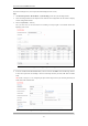
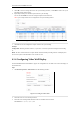
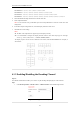
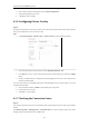
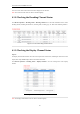
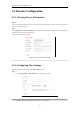
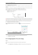
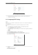
Table Of Contents
- CHAPTER 1 Introduction
- CHAPTER 2 Panels and Connections
- CHAPTER 3 Initial Network Parameters Configuration
- CHAPTER 4 Decoder Configuration and Operation by Web Browser
- 4.1 Decoding Operation
- 4.1.1 Configuring Decoded Video Display
- 4.1.2 Configuring Dynamic Decoding
- 4.1.3 Configuring Cycle Decoding
- 4.1.4 Configuring Video Wall Display
- 4.1.5 Enabling/Disabling the Decoding Channel
- 4.1.6 Configuring Picture Overlay
- 4.1.7 Checking the Connection Status
- 4.1.8 Checking the Decoding Channel Status
- 4.1.9 Checking the Display Channel Status
- 4.1.10 Configuring Transparent Channel
- 4.2 Decoder Configuration
- 4.2.1 Checking Device Information
- 4.2.2 Configuring Time Settings
- 4.2.3 Configuring Basic Network Settings
- 4.2.4 Configuring DDNS Settings
- 4.2.5 Configuring RS-485/RS-232 Serial Port
- 4.2.6 Configuring Alarm Input / Output Settings
- 4.2.7 Configuring Arming Time
- 4.2.8 Managing User Account
- 4.2.9 Importing/Exporting Parameters
- 4.3 Configuring Remote Playback
- 4.4 Switching Working Mode
- 4.5 Rebooting, Upgrading and Restoring the Default Settings for the Decoder
- 4.1 Decoding Operation
- CHAPTER 5 Decoder Configuration and Operation by Client Software
- CHAPTER 6 Appendix

User Manual of DS-6400HDI-T Decoder
22
5. Click OK to save the settings and back to the Cycle Decoding interface, or click Back to back to the Cycle
Decoding interface without saving.
6. Repeat Step4 and Step5 to edit other input streams for cycle decoding.
You can also click Delete to remove the configured input stream from the list.
Note: Up to 64 input streams can be configured for each cycle decoding channel.
Figure 4.11 Configure Input Streams for Decoding
7. Click Save to save the configuration of input streams for the cycle decoding.
Example:
Configuration: Decoding Channel: Channel 1, Cycle Time: 10 seconds, input streams configured for decoding:
10.
Result: the video streams from these 10 input channels will be decoded by decoding channel 1 and displayed on
the screen in sequence with the duration of 10 seconds for each.
4.1.4 Configuring Video Wall Display
The DS-6404/6408/6410/6412/6416HDI-T supports the configuration for the multi-screen video wall display of
the decoded video.
Steps:
1. Click Decode Operation > Video Wall to enter the following interface:
Figure 4.12 Configure Video Wall
2. Select the Screen No. from the drop-down list.
3. Select the Screen Jointing Mode. Different modes are selectable based on models:
DS-6404HDI-T: 1×2, 1×3, 1×4, 2×1, 2×2.