
User Manual
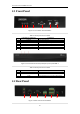
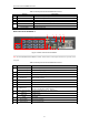
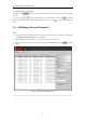
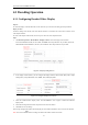
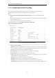
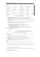
Table Of Contents
- CHAPTER 1 Introduction
- CHAPTER 2 Panels and Connections
- CHAPTER 3 Initial Network Parameters Configuration
- CHAPTER 4 Decoder Configuration and Operation by Web Browser
- 4.1 Decoding Operation
- 4.1.1 Configuring Decoded Video Display
- 4.1.2 Configuring Dynamic Decoding
- 4.1.3 Configuring Cycle Decoding
- 4.1.4 Configuring Video Wall Display
- 4.1.5 Enabling/Disabling the Decoding Channel
- 4.1.6 Configuring Picture Overlay
- 4.1.7 Checking the Connection Status
- 4.1.8 Checking the Decoding Channel Status
- 4.1.9 Checking the Display Channel Status
- 4.1.10 Configuring Transparent Channel
- 4.2 Decoder Configuration
- 4.2.1 Checking Device Information
- 4.2.2 Configuring Time Settings
- 4.2.3 Configuring Basic Network Settings
- 4.2.4 Configuring DDNS Settings
- 4.2.5 Configuring RS-485/RS-232 Serial Port
- 4.2.6 Configuring Alarm Input / Output Settings
- 4.2.7 Configuring Arming Time
- 4.2.8 Managing User Account
- 4.2.9 Importing/Exporting Parameters
- 4.3 Configuring Remote Playback
- 4.4 Switching Working Mode
- 4.5 Rebooting, Upgrading and Restoring the Default Settings for the Decoder
- 4.1 Decoding Operation
- CHAPTER 5 Decoder Configuration and Operation by Client Software
- CHAPTER 6 Appendix

User Manual of DS-6400HDI-T Decoder
11
Table 2.3 Description of DS-6401HDI-T Rear Panel
Rear Panel of DS-6416HDI-T
Figure 2.4 Rear Panel of DS-6416HDI-T
Note: For DS-6404/6408/6410/6412HDI-T models, 4/8/10/12 DVI-I video output connectors are provides on the
rear panel.
Table 2.4 Description of DS-6416HDI-T Rear Panel
1 2 3
4 7
6
8
9 10 11
12 13
5
Interface
Connections
1
LINE IN/OUT
Two-way audio input/output, 3.5mm connector.
2
LAN
10/100/1000 Mbps Ethernet interface
3
RS-232 Serial Interface
Connect to RS-232 devices, e.g., PC, etc.
4
RS-485 Serial Interface
Connect to RS-485 devices, e.g., keyboard, etc.
5
Alarm In
4 alarm inputs
Alarm Out
4 alarm outputs
6
Power Supply
12 VDC power input
Interface
Connections
1
VGA Video Input
VGA video input
DVI-I Video Input
DVI-I video input ( support DVI-to-VGA adapter)
2
DVI-I Video Output
DVI output of decoded video
3
LINE IN/OUT
Two-way audio input/output, 3.5mm connector.
4
AUDIO OUT
DB15 connector for audio out, connecting to audio output device with the
DB15-to-BNC adapter.
5
LAN
10/100/1000 Mbps Ethernet interface
6
USB Interface
Reserved
7
RS-232 Serial Interface
Connect to RS-232 devices, e.g., PC, etc.
8
VIDEO OUT
DB15 connector for video output, connecting to video output device (e.g.,
monitor) with the DB15-to-BNC adapter.
9
RS-485 Serial Interface
Connect to RS-485 devices, e.g., keyboard, etc.
10
Alarm In
4 alarm inputs
Alarm Out
4 alarm outputs
11
GND
Grounding
12
Power Supply
Power input interface
13
Power Switch
Power On/Off Switch