HD Video/Audio Decoder User Manual UD.
User Manual of DS-6400HDI-T Decoder User Manual©2015 Hangzhou Hikvision Digital Technology Co., Ltd. This user manual is intended for users of Decoder (“Product”). It includes instructions on how to use the Product. The software embodied in the Product is governed by the user license agreement covering that Product. About this Manual This Manual is subject to domestic and international copyright protection. Hangzhou Hikvision Digital Technology Co., Ltd. (“Hikvision”) reserves all rights to this manual.
User Manual of DS-6400HDI-T Decoder Regulatory information FCC information FCC compliance: This equipment has been tested and found to comply with the limits for a digital device, pursuant to part 15 of the FCC Rules. These limits are designed to provide reasonable protection against harmful interference when the equipment is operated in a commercial environment.
User Manual of DS-6400HDI-T Decoder Preventive and Cautionary Tips Before connecting and operating your device, please be advised of the following tips: • • • • • Ensure unit is installed in a well-ventilated, dust-free environment. Unit is designed for indoor use only. Keep all liquids away from the device. Ensure environmental conditions meet factory specifications. Ensure unit is properly secured to a rack or shelf.
User Manual of DS-6400HDI-T Decoder Table of Contents CHAPTER 1 Introduction ........................................................................................................ 6 1.1 Description ...................................................................................................................... 7 1.2 Features ........................................................................................................................... 7 CHAPTER 2 Panels and Connections ..................
User Manual of DS-6400HDI-T Decoder 4.2.8 Managing User Account ......................................................................................... 33 4.2.9 Importing/Exporting Parameters ............................................................................ 34 4.3 Configuring Remote Playback ...................................................................................... 36 4.3.1 Normal Playback .............................................................................................
User Manual of DS-6400HDI-T Decoder CHAPTER 1 Introduction 6
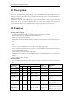
User Manual of DS-6400HDI-T Decoder 1.1 Description Designed for the high-definition video monitoring system, DS-6400HDI-T Series HD Video/Audio Decoder is developed on the basis of TI platform, Linux operating system and Netra processor, ensuring high reliability and stability of system running.
User Manual of DS-6400HDI-T Decoder Decoding Mode Dynamic decoding: Log on the remote encoder or remote stream media server to select a channel of video source to acquire video stream, and then decode and output the video for local display. Cycle decoding: Set multiple remote monitoring channels on a decoding channel, and the decoder is capable of performing cycle decoding according to the configured sequence and time.
User Manual of DS-6400HDI-T Decoder CHAPTER 2 Panels and Connections 9
User Manual of DS-6400HDI-T Decoder 2.1 Front Panel 1 2 3 4 5 6 7 Figure 2.1 Front Panel of DS-6401HDI-T Table 2.1 Description of Front Panel 1 2 3 4 5 6 7 LED Indicator & Interface Connections POWER LINK Tx/Rx HDMI Video Output VGA Video Output Audio Output Video Output Power LED indicator Network connection LED indicator Data transmitting/receiving status LED indicator HDMI output of decoded video VGA output of decoded video Audio output, 3.5mm connector Video output, BNC connector Figure 2.
User Manual of DS-6400HDI-T Decoder Table 2.3 Description of DS-6401HDI-T Rear Panel Interface LINE IN/OUT LAN RS-232 Serial Interface RS-485 Serial Interface Alarm In Alarm Out Power Supply 1 2 3 4 5 6 Connections Two-way audio input/output, 3.5mm connector. 10/100/1000 Mbps Ethernet interface Connect to RS-232 devices, e.g., PC, etc. Connect to RS-485 devices, e.g., keyboard, etc.
User Manual of DS-6400HDI-T Decoder CHAPTER 3 Initial Network Parameters Configuration 12
User Manual of DS-6400HDI-T Decoder Purpose: If you don’t know the IP address of the decoder and this is not the first time you use the decoder, you can use SADP (IP finder) software or the Serial port tools to find out the IP address of the decoder and to configure the IP address or other network parameters of it. It is recommended to change the default IP address for the first time to use it.
User Manual of DS-6400HDI-T Decoder Search online devices manually You can also click to the list. Note: You can click to refresh the online device list manually. The newly searched devices will be added or on each column heading to order the information; you can click device table and hide the network parameter panel on the right side, or click to expand the to show the network parameter panel. 3.2 Modifying Network Parameters Steps: 1.
User Manual of DS-6400HDI-T Decoder CHAPTER 4 Decoder Configuration and Operation by Web Browser 15
User Manual of DS-6400HDI-T Decoder Purpose: Since there is no local operation GUI provided for the decoder, you can manage and configure it by web browser or the iVMS-4200 client software. In this chapter, the operation and management of the decoder by the web browser is provided. Note: The tested Web browsers include: IE7 and IE8, chrome, safari and firefox4. Open the Web browser and input the IP address of Decoder (e.g., http://192.168.0.0) to enter the login page: Figure 4.
User Manual of DS-6400HDI-T Decoder 4.1 Decoding Operation 4.1.1 Configuring Decoded Video Display Purpose: To realize the display of the decoded video on the video wall, you must set the decoding operation parameters. Before you start: Check the cabling of the decoder, and ensure that the decoder is connected to the video wall or monitor via the video output interfaces. To set the video output of the decoder, the first step is to choose the video output interfaces. Steps: 1.
User Manual of DS-6400HDI-T Decoder 4.1.2 Configuring Dynamic Decoding After you have configured the decoded video display mode, you can enable the dynamic decoding now. Dynamic decoding means that you decode one channel for one decoding window. Steps: 1. Click Decode Operation > Decode Mode > Dynamic Decoding to enter the dynamic decode settings interface. 2. Select a decoding channel from the drop-down list which has been configured for the sub-window in Display Control Configuration interface. 3.
User Manual of DS-6400HDI-T Decoder Figure 4.6 Set Channel Type Remote Host Channel No.: Enter the channel No. of the encoding device for decoding. User Name/Password: Enter the user name and password used for login to the encoding device. Transmission Protocol: Select the network transmission protocol to TCP, UDP or Mcast. The default protocol is TCP. Stream Type: Set the stream type to be decoded and the default type is main stream.
User Manual of DS-6400HDI-T Decoder Figure 4.8 Set Encoding Device by DDNS Configure the following settings: Domain Name: Input the registered domain name of the DDNS server for the encoding device for decoding. Domain Name Server Type: Select the DDNS server type. Currently only the HiDDNS is available. DDNS Server Address: Input the address of the DDNS server (www.hik-online.com). DDNS Server Port: Input the port number of the DDNS server (e.g., 80).
User Manual of DS-6400HDI-T Decoder (the remote encoding devices) to one output (the channel displayed on the screen). Steps: 1. Click Decode Operation > Decode Mode > Cycle Decoding to enter the Cycle Decoding interface. 2. Select a decoding channel from the drop-down list which has been configured for the sub-window in Display Control Configuration interface. 3. Enter the Cycle Time (1~1000 sec).
User Manual of DS-6400HDI-T Decoder 5. Click OK to save the settings and back to the Cycle Decoding interface, or click Back to back to the Cycle Decoding interface without saving. 6. Repeat Step4 and Step5 to edit other input streams for cycle decoding. You can also click Delete to remove the configured input stream from the list. Note: Up to 64 input streams can be configured for each cycle decoding channel. Figure 4.11 Configure Input Streams for Decoding 7.
User Manual of DS-6400HDI-T Decoder DS-6408HDI-T: 1×2, 1×3, 1×4, 2×1, 2×2, 2×3, 3×2, 2×4, 4×2. DS-6410HDI-T: 1×2, 1×3, 1×4, 2×1, 2×2, 2×3, 2×4, 2×5, 3×2, 3×3, 4×2, 5×2. DS-6412HDI-T: 1×2, 1×3, 1×4, 2×1, 2×2, 2×3, 2×4, 2×5, 3×2, 3×3, 4×2, 5×2, 3×4, 4×3. DS-6416HDI-T: 1×2, 1×3, 1×4, 2×1, 2×2, 2×3, 2×4, 2×5, 3×2, 3×3, 4×2, 5×2, 3×4, 4×3, 5×3, 3×5, 4×4. 4. Select the Related Decoding Channel for the selected video wall. 5. Set the Output Resolution.
User Manual of DS-6400HDI-T Decoder 2. Select a decode channel in the drop-down list in the Decode Channel field. 3. Set the decoding channel to On or Off. 4. Click Save to save the settings. 4.1.6 Configuring Picture Overlay Purpose: The Picture Overlay function can overlay a picture on the screen for the selected decode channel, and the position of the picture overlaid on the screen can also be set here. Steps: 1.
User Manual of DS-6400HDI-T Decoder You can view the status of the network connection displayed on the interface. Note: The connection status of device will be refreshed regularly. 4.1.8 Checking the Decoding Channel Status Click Decode Operation > Decoding Status > Decoding Channel to view the status information of the current decoding channel, including the channel No., decoding status, encoding type, etc. Refer to the following interface: Figure 4.16 Check Decoding Channel Status 4.1.
User Manual of DS-6400HDI-T Decoder 4.1.10 Configuring Transparent Channel The Transparent Channel refers to the transmission channel used for forwarding data between the Decoder and the Encoder without operating on the data transferred. Steps: 1. Click Decode Operation > Transparent Channel to enter the Transparent Channel settings interface. 2. Click to select a transparent channel from the list to configure. Figure 4.18 Configure Transparent Channel 3.
User Manual of DS-6400HDI-T Decoder 4.2 Decoder Configuration 4.2.1 Checking Device Information Purpose: You can check the information of the device in the device information interface, such as the Device Type, Device Serial No., Firmware Version, etc. Steps: Click Configuration > Device Information to view the device information, including the Device Type, Device Serial No., Firmware Version, DSP Version, etc. Note: The device name can be edited. Figure 4.20 Check Device Information 4.2.
User Manual of DS-6400HDI-T Decoder Configuring Time Sync by NTP Server A Network Time Protocol (NTP) Server can be configured on your device to ensure the accuracy of system date/time. If the device is connected to a Dynamic Host Configuration Protocol (DHCP) network that has time server properties configured, the camera will synchronize automatically with the time server. Enable the NTP function by checking the checkbox, and configure the following settings: NTP Server: IP address of NTP server.
User Manual of DS-6400HDI-T Decoder Figure 4.24 Configure Basic Network Settings 2. Set the network parameters, including the IP Address, Subnet Mask, Gateway and DNS Server. 3. Click Save to save the settings. 4.2.4 Configuring DDNS Settings Purpose: If your device is set to use PPPoE as its default network connection, you may set Dynamic DNS (DDNS) to be used for network access. Prior registration with your DDNS Provider is required before configuring the system to use DDNS. Steps: 1.
User Manual of DS-6400HDI-T Decoder Note: For the IP Server, You have to apply a static IP, subnet mask, gateway and primary DNS from the ISP. The Server Address should be entered with the static IP address of the PC that runs IPServer software. Figure 4.26 IPServer Settings • PeanutHull: (1) Enter User Name and Password obtained from the PeanutHull website. (2) Click Save to save the settings. Figure 4.27 PeanutHull Settings • HiDDNS: (1) Enter the Server Address of the HiDDNS server: www.hik-online.
User Manual of DS-6400HDI-T Decoder Figure 4.28 HiDDNS Settings Note: After having successfully registered the device on the HiDDNS server, you can access your device via web browser or Client Software with the Device Domain Name (Device Name). 4.2.5 Configuring RS-485/RS-232 Serial Port Configuring RS-232 Parameters Steps: 1. Click Configuration > Serial Port Settings > RS-232 Port to enter the following interface: Figure 4.29 Configure RS-232 Settings 2.
User Manual of DS-6400HDI-T Decoder 1. Click Configuration > Serial Port Settings > RS-485 Port to enter the following interface: Figure 4.30 Configure RS-485 Settings 2. Configure the RS-485 parameters, including the baud rate, data bit, stop bit and parity type. 3. Click Save to save the settings. 4.2.6 Configuring Alarm Input / Output Settings Purpose: As the Decoder is unable to obtain the alarm signal over network, it must be connected with external alarm input/output.
User Manual of DS-6400HDI-T Decoder seconds, when an alarm occurs the alarming time lasts 10 seconds later than the time of the alarm stopped. 3. Click Save to save your settings. Figure 4.32 Configure Alarm Output Settings 4.2.7 Configuring Arming Time Purpose: Set the time schedule for alarm input and alarm output. Steps: 1. Click Configuration > Arming Time to enter the following interface. Figure 4.33 Configure Arming Time 2. Choose the Start Time and the End Time. 3.
User Manual of DS-6400HDI-T Decoder 1. Click Configuration > User Management to enter the account management interface. 2. You can add, modify or delete the user account, as well as configure operating permissions for each user account. Figure 4.34 Configure User Account Note: For the admin user, only the password can be modified. The default password (12345) for the Admin account is for first-time log-in purposes only.
User Manual of DS-6400HDI-T Decoder Figure 4.35 Import/Export Config File 2. Click Browse to select the file from the local directory and then click the Import button to import a configuration file. Or click the Export button to export configuration files to the local backup device.
User Manual of DS-6400HDI-T Decoder 4.3 Configuring Remote Playback Purpose: You can play back the record files stored in the remote encoding devices. 4.3.1 Normal Playback Steps: 1. Click Decode Operation >Remote Playback to enter the remote playback interface: Figure 4.36 Configure Remote Playback 2. Select a Decoding Channel from the drop-down list for playback. 3. You can playback the video files of the encoding device by IP Mode or DDNS mode.
User Manual of DS-6400HDI-T Decoder Task 2: Playback Video Files of the Encoding Device by DDNS Mode 1) Check the checkbox of DDNS Mode. 2) Enter the Domain Name of the device. You can register the alias of the device domain name in the HiDDNS server first and then enter the alias to the domain name in the decoder; you can also enter the domain name directly on the decoder to create a new one.
User Manual of DS-6400HDI-T Decoder During the playback, use the buttons to start playing, stop playing, slow forward, fast forward, and turn on audio respectively. Figure 4.40 Playback Control Notes: The speed of slow forward can be set to 1/2X, 1/4X and 1/8X; and the speed of fast forward can be set to 2X, 4X and 8X. The speed of fast forward and slow forward is not supported in the VCA playback mode.
User Manual of DS-6400HDI-T Decoder 4.4 Switching Working Mode Steps: 1. Click Device Management to enter the device management interface. 2. Click the to enter the Switch Mode interface. Two working modes are selectable: Channel Mode and VCA Mode. When the VCA Mode is selected, the VCA decoding is enabled. Figure 4.41 Switch Display Mode 3. Click OK to save the settings. Note: The device will automatically restart after mode switch. Figure 4.
User Manual of DS-6400HDI-T Decoder 4.5 Rebooting, Upgrading and Restoring the Default Settings for the Decoder Steps: 1. To reboot, upgrade or restore the default settings of the decoder, go to the Device Management interface. 2. Choose the configuration items in the left part of the page. To upgrade the decoder: 1) Click the icon to enter the interface, see the following figure. 2) Click Browse to search the upgrading files. 3) Click Upgrade to upgrade it. Figure 4.
User Manual of DS-6400HDI-T Decoder To reboot the decoder: 1) Click icon to enter the rebooting interface. 2) Click OK if you are sure to reboot the device. Figure 4.
User Manual of DS-6400HDI-T Decoder CHAPTER 5 Decoder Configuration and Operation by Client Software 42
User Manual of DS-6400HDI-T Decoder Run the disk of iVMS-4200 software, and double click the icon to install it in your PC. In this chapter, the basic procedure of operating the decoder by the software is described. Please refer to the user manual of iVMS-4200 for more detailed information. The following figure shows the main interface after accessing to the software: Figure 5.
User Manual of DS-6400HDI-T Decoder Figure 5.2 Add Device by IP Address Note: Please refer to the User Manual of iVMS-4200 for detailed instructions of adding encoding/decoding device. The successfully added decoder device can be viewed in the list. Figure 5.
User Manual of DS-6400HDI-T Decoder 5.2 Setting Video Wall Layout Steps: 1. In the control panel, click 2. Click the to enter the Video Wall setting interface. to enter the video wall layout configuration. Figure 5.4 Video Wall Layout Settings 3. You can use the default video wall layout or click to add new layout. Figure 5.5 Add Screen Information 4. Edit the video wall name, and enter the number of screens in row and column. 5. Click Add to finish the adding of the video wall information.
User Manual of DS-6400HDI-T Decoder Notes: Up to 4 video walls can be added to the client software. The total number of the display windows of the video wall should be no more than 100. The ranges of the row number and column number are both between 1 and 10. 6. Click and drag the output channels on the list of the decoding devices to the display screens. Figure 5.
User Manual of DS-6400HDI-T Decoder Figure 5.7 Multi-screen Display (1) 3. Click to confirm jointing the screens. Figure 5.8 Multi-screen Display (2) 4. (Optional) You can set the resolution for the jointed window by right-clicking on it and select Decoding Output Configuration. To cancel the multi-screen display, click in the upper-right corner of the display window. Figure 5.9 Modify Output Parameters 5.
User Manual of DS-6400HDI-T Decoder Note: After enable decoding and displaying, the captured picture of the video from the encoding device displays on the Video Wall interface. And the real-time live view is shown on the physical video wall. 5.4.1 Decoding and Displaying Video Steps: 1. Click Back to Operation Page to go back to the Video Wall Operation interface. Figure 5.10 Video Wall Operation Page 2. Click-and-drag the camera on the left-side list to the display window of video wall.
User Manual of DS-6400HDI-T Decoder Figure 5.11 Right-click Menu Stop / Start Decoding: Stop / Start the decoding. Start / Pause Successive Decoding: Start / Pause the cycle decoding. This function is only supported by decoder. Refresh: Refresh the decoding. Open / Close Digital Zoom: Enable / Disable digital zoom. Enable Audio: Turn on / off the audio of the decoding video. Enlarge Window: Display the window in full-screen mode.
User Manual of DS-6400HDI-T Decoder Stop all the decoding Stop all the roaming windows Refresh all the decoding windows Set cycle decoding and switching interval 5.4.3 Configuring Playback Purpose: The record file is supported to be played back on the video wall. Note: playback function is only supported by decoder. Steps: 1. Click-and-drag the camera on the left-side list to the display window of video wall, or you can open a window if supported. 2.
User Manual of DS-6400HDI-T Decoder The VCA (Video Content Analysis) devices can be added to the client for management, including VCA resource allocation, shield region settings, rule settings, VCA alarm settings, etc. 5.5.1 Allocating VCA Resource Before you start: Before you set the VCA configuration for the added device, you need to configure the VCA resource of the device to enable the VCA function of the corresponding cameras. Steps: 1.
User Manual of DS-6400HDI-T Decoder 3. Click the icon, then click and drag the mouse to draw the region, and right-click to finish drawing. 4. (Optional) Click to select an added shield region, and click 5. Click Save to save the settings. to delete it. Figure 5.15 Set Shield Region 5.5.3 VCA Rule Configuration Steps: 1. In the VCA Config interface, click the Rule tab to set the VCA rules. 2. Check the corresponding checkbox to enable the rule.
User Manual of DS-6400HDI-T Decoder Draw the minimum size filter. Note: The rule and the size filter should be enabled. / Start/Pause the live view of the camera. Set the rule Task1: Draw the virtual line (only for Line Crossing) 1 4 3 Figure 5.16 Draw the Virtual Line Steps: 1. Please make sure the rule is enabled and the Rule Type is set as the “Line Crossing” in the area 1 in the above figure. 2.
User Manual of DS-6400HDI-T Decoder 1 4 2 3 Figure 5.17 Draw the Arming Region Steps: 1. Please make sure the rule is enabled in the area 1 in the above figure. 2. To draw a rectangle, click the icon in the area 2 and click to set the top left corner (bottom right corner) of the region in the area 3 and move the mouse to the bottom right corner (top left corner) and click again.
User Manual of DS-6400HDI-T Decoder Figure 5.18 Set the VCA Alarm 2. Upload Picture: enable Upload Picture by checking the checkbox, and you can set the quality and resolution of the VCA picture uploaded to the client software. Overlay VCA Alarm Logo: enable Overlay VCA Alarm Logo by checking the checkbox, and set the value of the X-coordinates and Y-coordinates for displaying the VCA alarm logo. Flicker: enable the VCA logo in flickering mode as demand, and set the flickering time.
User Manual of DS-6400HDI-T Decoder CHAPTER 6 Appendix 56
User Manual of DS-6400HDI-T Decoder Appendix A. Specifications Model DS-6401HDI-T 1-ch VGA Output 1920×1080@60Hz, 1600×1200@60Hz, 1280×1024@60Hz, 1280×720@50/60Hz, 1024×768@60Hz 1-ch Audio/ Video Output Audio/ Video Decoding VCA Decoding External Interface General HDMI Output 1920×1080@60/50HZ, 1600×1200@60Hz, 1280×1024@60Hz, 1280×720@50/60Hz, 1024×768@60Hz CVBS Output (without audio) 1-ch Audio Output 1-ch, RCA connector Video Stream Supported Format Audio Stream Supported Format H.
User Manual of DS-6400HDI-T Decoder Model Audio/ Video Input/Output Audio/ Video Decoding VCA Decoding External Interface General DS-6404HDI-T DS-6408HDI-T 4-ch 8-ch DVI Output 1920×1080@60/50Hz, 1600×1200@60Hz, 1280×1024@60Hz, 1280×720@50/60Hz, 1024×768@60Hz CVBS Output (without audio) 1-ch DB15 connector (used with the DB15-to-BNC adapter) 1-ch, VGA connector; 1-ch, DVI-I connector Video Input 1920×1080@60/50Hz, 1600×1200@60Hz, 1280×1024@60Hz, 1280×720@50/60Hz, 1024×768@60Hz, 1280*800@60Hz
User Manual of DS-6400HDI-T Decoder Model Audio/ Video Input/ Output Audio/ Video Decoding VCA Decoding External Interface General DS-6410HDI-T DS-6412HDI-T DS-6416HDI-T 10-ch 12-ch 16-ch DVI Output 1920×1080@60/50Hz, 1600×1200@60Hz, 1280×1024@60Hz, 1280×720@50/60Hz, 1024×768@60Hz CVBS Output (without audio) 5-ch 6-ch 8-ch DB15 connector (used with the DB15-to-BNC adapter) 1-ch, VGA connector; 1-ch, DVI-I connector Video Input 1920×1080@60/50Hz, 1600×1200@60Hz, 1280×1024@60Hz, 1280×720@
User Manual of DS-6400HDI-T Decoder Appendix B. FAQ Why cannot ping the decoder? 1. Check the cable and the switch. 2. Please refer to Chapter 3 to configure the IP address of the decoder. Why cannot connect the decoder with client software? 1. Check the decoder IP address. 2. Cable is connected. 3. User name and password of decoder are correct. Why cannot play back the record files in DVR with decoder? 1. Check the DVR network connection. 2.
User Manual of DS-6400HDI-T Decoder Appendix C. List of Third-party IP Cameras Access IP Camera Manufacturer Model Supported Video Format SP306H Panasonic SP336H SNC-CH220 Sony SNC-RH124 P5532 Axis Q7404 Sanyo VCC-HD2500P Bosch NBC265P Zavio D5110 Arecont AC1305M Pelco IX30DN-ACFZHB3 Onvif Supported 61 H.